background image

i

PREFACE

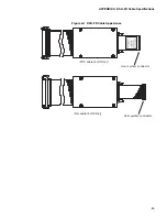
Thank you for purchasing the LQFP-144P


*

1

 header type 9 for the DSU-FR*

2

 emulator (model num-

ber : MB2198-161-E).
The MB2198-161-E is used with the adapter unit for connecting to user systems that use the MB91
(F) 475 (LQFP-144P) series of Fujitsu FR microcontrollers, together with the DSU-FR emulator
(model number : MB2198-01-E)*

3

 and DSU-FR cable (model number : MB2198-10-E)*

4

The manual explains how to handle the MB2198-161-E. Before using the MB2198-161-E, be sure
to read this manual.
Please contact sales or support representative for details on the mass production and evaluation MCU
models that can be used with this product.

*1 :  Uses the FPT-144P-M12 package (lead pitch: 0.4mm, body size: 16mm 

×

 16mm)

*2 :  FR, the abbreviation of FUJITSU RISC controller, is a line of products of FUJITSU MICRO-

ELECTRONICS Limited.

*3 :  Referred to as “emulator”.

*4 :  Referred to as “DSU cable”.

Handling and Use

Please refer to the following manuals for information about how to handle and use this product and
also for details on safety precautions.

DSU-FR EMULATOR MB2198-01-E OPERATION MANUAL

DSU-FR EMULATOR DSU-FR CABLE MB2198-10-E OPERATION MANUAL

DSU-FR EMULATOR BGA-224P ADAPTER MB2198-160-E OPERATION MANUAL

European RoHS Compliance

Products with a “-E” suffix on the part number are European RoHS compliant products.

Notice on this document

All information included in this document is current as of the date it is issued. Such information is
subject to change without any prior notice.
Please confirm the latest relevant information with the sales representatives.

Cautions Regarding the Products Described in this Document

The following precautions apply to the product described in this manual.

CAUTION

Indicates a feature that, if not used correctly, may result in minor or moderate in-
juries, and which may cause the customer system to malfunction.

Cuts

This product has parts with sharp points that are exposed.
Do not touch edge of the product with your bare hands.

Damage

When connect the header board to the user system, correctly position the index 
mark (

) on the NQPACK mounted on the user system with the index mark (

on the header board, otherwise the emulator system and user system might be 
damaged.

Damage

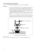
When mounting a mass production MCU, correctly position pin 1, otherwise the 
mass production MCU and user system might be damaged.

Содержание MB2147-01

Страница 1: ...Confidential How to Install Update USB Driver for the Fujitsu MB2147 01 and MB2198 01 Emulator System Application Note ...

Страница 2: ...ion 1 Difference from the Previous USB DriverVersion 1 USB Driver Uninstallation Procedure 2 USB Driver Installation Procedure 3 Driver Confirmation 3 USB Driver Installation from Found New HardwareWizard 4 Restoring the Previous Driver 4 Common USB Driver Errors and Possible Solutions 5 ...

Страница 3: ...e for the USB driver version 9 0 installations on both the MB2147 01 F2MC 16LX emulator and MB2198 01 F2MC 16FX and 32 bitFRemulator andhowtoroll backtothepreviousversionif required USB DriverVersion The current USB driver version is 9 01 Prior to this Softune Workbenchhastwopreviousversionsof theUSBdriver version 7 02 and 1 4 0 1 The current installed version of the driver can be checked with a d...

Страница 4: ...before installing the USB driver version 9 01 The uninstallation procedures of the previous driver are as follows Connect ICE with PC in USB and turn ON the emulator When the previous driver is installed the following is displayed in the device manager USB or Jungo USB FUJITSU USB Driver for ICE or Jungo FUJITSU USB Driver for ICE Note When the above description is not displayed install the driver...

Страница 5: ...the batch file drv_install drv_install bat from the command line In this case make the driver directory to the current directory on the command prompt Now the installation of the USB driver is completed Driver Confirmation To confirm whether USB driver is correctly installed by the above procedures check the driver file windrvr6 sys in the detailed dialogof USB FUJITSUUSBDriverforICE of Devicemana...

Страница 6: ...ver should be performed In this case use the USB driver package WinDriver ver 7 02 or earlier The procedure is shown as follows 1 Copy SiUSB dll of the previous version to the following directory 1 1 Under the bin of SOFTUNE installation directory 2 Copy wd_utils dll to the following directory 2 2 windir system32 windir is a directory path defined in the system environment variable of Windows syst...

Страница 7: ... installed properly the Softune Workbench will show an error as Invalid communication when trying to connect with the Emulator system In this case it is required to reconfirm the driver installation and version If the problem doesn t solve by reinstallation then it is required to roll back to previous driver In some systems the USB driver installation will pop up even though the driver has been al...

Страница 8: ...nia 94085 5401 Tel 800 866 8608 Fax 408 737 5999 E mail inquiry fma fujitsu com Web Site http us fujitsu com micro 2008 Fujitsu Microelectronics America Inc All rights reserved All company and product names are trademarks or registered trademarks of their respective owners Printed in U S A MCU AN 21299 4 2008 ...

Страница 9: ...FUJITSU SEMICONDUCTOR CONTROLLER MANUAL DSU FR EMULATOR MB2198 01 HARDWARE MANUAL CM71 00413 2E ...

Страница 10: ......

Страница 11: ...FUJITSU LIMITED DSU FR EMULATOR MB2198 01 HARDWARE MANUAL ...

Страница 12: ......

Страница 13: ...The MB2198 01 is a development support tool used to develop and evaluate application products that use microcontrollers of the FR family This manual is intended for engineers who use the MB2198 01 hereafter called the emulator to develop application products with Fujitsu FR family microcontrollers The manual explains how to handle and connect the emulator Trademarks FR is the abbreviation of FUJIT...

Страница 14: ...ed Do not attempt to repair the product by yourself Otherwise personal injury damage to the product or other property damage may result Using such a product without having it properly repaired may result in fire or electric shock 15 If water or other liquid a metallic object or other foreign matter enters the product immediately turn off power and disconnect the power plug from the outlet Then con...

Страница 15: ... in a fire 17 19 Do not insert metallic combustible or other objects or allow them to drop into the product through a ventilation hole or other opening Doing so may result in device problems fire or electric shock 17 Do not use a voltage other than the indicated value of supply voltage Do not connect power cable together with too many plugs to an outlet Doing so may result in fire or electric shoc...

Страница 16: ...e the product in a location such as near a speaker or television tuner where it is exposed to an electromagnetic field Doing so may result in device problems 18 Make sure that power to the product is turned off and the power plug is disconnected from outlets before connecting or disconnecting cables or removing or mounting boards unless such an operation uses USB cables for plug and play devices D...

Страница 17: ...e product is turned off and the power plug is disconnected from outlets before connecting or disconnecting cables unless such an operation uses USB cables for plug and play devices Doing so may result in device problems or electric shock 31 Follow the procedure described in the manual to turn on the product Doing so may result in device problems 39 After power is turned on to the product do not mo...

Страница 18: ...OD This chapter explains how to connect the emulator CHAPTER 3 OPERATION METHOD This chapter explains how to operate the emulator and provides procedures for powering on and off the emulator Read this chapter thoroughly before powering on the emulator APPENDIX The appendix contains DSU FR cable specifications and user system specifications Related Manual See also the following manual Hardware Manu...

Страница 19: ...rein The products described in this document are designed developed and manufactured as contemplated for general use including without limitation ordinary industrial use general office use personal use and household use but are not designed developed and manufactured as contemplated 1 for use accompanying fatal risks or dangers that unless extremely high safety is secured could have a serious effe...

Страница 20: ...viii ...

Страница 21: ...ons on Possible Problems 15 1 12 Precautions on Handling the Emulator 16 1 13 Precautions on Use 19 CHAPTER 2 CONNECTION METHOD 21 2 1 System Configuration 22 2 2 Connection of DSU FR Cable to Attached Cable 23 2 3 Connection of User System 26 2 4 Connection of DSU FR Cable 29 2 5 Connection of Adapter Board 30 2 6 Connection of Host Machine 31 2 7 Connection of AC Adapter 32 2 8 Connection of Tes...

Страница 22: ...x ...

Страница 23: ...product 1 1 Checking Packed Components 1 2 Appearance and Part Names 1 3 General Specifications 1 4 RS 232C Port Specifications 1 5 USB Port Specifications 1 6 LAN Port Specifications 1 7 External Trigger Input Terminal Specifications 1 8 Program Execution Output Terminal Specifications 1 9 Power on Debug Specifications 1 10 Options 1 11 Precautions on Possible Problems 1 12 Precautions on Handlin...

Страница 24: ...Before using the emulator make sure that the following packed components have been delivered DSU FR emulator 1 AC adapter 1 AC cord 1 Hardware manuals 1 each in Japanese and in English this manual Note The AC cord and AC adapter are packed in the same box To re transport the product use the package used at the delivery and pack them as it was packed Doing so may result in damage to the product CAU...

Страница 25: ...view No Name Description Status indicator LCD Displays a variety of information including settings communication status and operation status 1 Goes on when emulator power is supplied POWER LED UVCC LED Goes on when user system power UVcc is supplied Setting switch Used to change settings and the information displayed on the status indicator LCD 1 Adapter board connector Accepts the connection of d...

Страница 26: ...t of external trigger signals EMUL terminal Terminal that outputs program execution signals No Name Description Reset switch Reset switch for the emulator system Power switch Power switch for the emulator DC inlet Inlet in which to plug the AC adapter USB connector Connector for a USB cable RS 232C connector Connector for a RS 232C cable TEST terminal Terminal for testing the product Do not use th...

Страница 27: ...tem power input 2 0 V to 5 5 V UVCC 100 mA or less Operating frequency Maximum of 33 MHz 3 Operating temperature 5 to 35 Operating humidity 20 to 80 No condensation External dimensions 148 W x 210 D x 44 H mm not including protrusions and rubber pads Weight 700 g 1 Use this only if the evaluation MCU has a DSU dedicated power input terminal Do not use this terminal for any other purpose The emulat...

Страница 28: ...ee Section 1 10 Options Figure 1 4 1 RS 232C Connector Circuit Configuration Table 1 4 1 RS 232C Port Specifications Item Description Connector type D Sub 9 pin male Signal definition DTE same as for a personal computer Baud rate 9600 19 2 K 115 2 K bps Data bit length 8 bits Stop bit length 1 bit Parity bit None X control None The possible values depend on the emulator debugger specifications For...

Страница 29: ... cable USB Port Specifications Table 1 5 1 USB Port Specifications lists the USB port specifications Table 1 5 1 USB Port Specifications Item Description Applicable standard USB 1 1 Communication protocol Full Speed Bulk Transfer Data transfer rate 12 Mbps Connector type Series B Power Self Powered ...

Страница 30: ...able 1 6 1 LAN Port Specifications lists the LAN port specifications Table 1 6 1 LAN Port Specifications Item Description Applicable standard IEEE 802 3 Communication protocol TCP IP Data transfer rate 10 Mbps 100 Mbps Connector type Series B IP address Variable Port address Variable Ethernet address Global Fixed registered with IEEE Local Variable ...

Страница 31: ...ion Notes Regarding Use of the External Trigger Input Pin Before using the external trigger function be sure that you understand the following break slip characteristics The trigger signal entered from the external trigger input pin is transmitted to the evaluation MCU after being synchronized with the operating frequency of the emulator interface in the emulator The operating frequency of the emu...

Страница 32: ...inal Specifications lists the program execution output terminal specifications Figure 1 8 1 Program Execution Output Terminal Circuit Configuration shows the circuit configuration Figure 1 8 1 Program Execution Output Terminal Circuit Configuration Table 1 8 1 Program Execution Output Terminal Specifications Terminal name Input or output Description EMUL Output User program execution signals are o...

Страница 33: ...evaluation MCU must be compatible with the power on debug function For more information contact the Fujitsu Sales Dept or Support Dept 2 The name of the reset terminal may depend on the model of the evaluation MCU For more information contact the Fujitsu Sales Dept or Support Dept Operation Flow Figure 1 9 1 Power on Debug Operation Flow shows the flow of the power on debug operation Figure 1 9 1 ...

Страница 34: ...higher the emulator checks whether voltage is maintained at the power on detection level or higher during the operation stabilization time about 10 ms of the evaluation MCU See 2 of Figure 1 9 2 Timing of Power on Debug Operation Reset cancellation The reset terminal is controlled After the operation stabilization time has elapsed INIT terminal output of the evaluation MCU is switched to reset inp...

Страница 35: ...u Sales Dept or Support Dept Explanations involving a DSU FR cable in this manual are referring to the MB2198 10 3 The adapter board and header board are an interface board that connects the user system to the emulator unit Purchase an adapter board and header board that are compatible with the evaluation MCU used Contact the Fujitsu Sales Dept or Support Dept for information on selecting a suitab...

Страница 36: ... Figure 1 10 1 Interlink Cable Wiring SHELL SHELL 7 RTS 8 CTS 6 DSR 5 GND 4 DTR 3 TXD 2 RXD 1 DCD 9 RI RTS 7 CTS 8 DSR 6 GND 5 DTR 4 TXD 3 RXD 2 DCD 1 RI 9 Personal computer side D sub 9 pin female connector Emulator side D sub 9 pin female connector ...

Страница 37: ...t Then contact our sales or support department to request that the product be repaired Do not attempt to repair the product by yourself Otherwise personal injury damage to the product or other property damage may result Using such a product without having it properly repaired may result in fire or electric shock If water or other liquid a metallic object or other foreign matter enters the product ...

Страница 38: ...evice problems Disconnect the power plug during electrical storms Using the product during an electrical storm may result in damage to the product or fire Do not open the product case Do not modify the product without permission Doing so may result in device problems fire or electric shock Do not use the product near water such as near a bath or shower Doing so may result in device problems fire o...

Страница 39: ...eat possibly resulting in a fire Do not insert metallic combustible or other objects or allow them to drop into the product through a ventilation hole or other opening Doing so may result in device problems fire or electric shock Do not use a voltage other than the indicated value of supply voltage Do not connect power cable together with too many plugs to an outlet Doing so may result in fire or ...

Страница 40: ...or a location that is not level or stable Doing so may result in device problems or the product falling over or falling on the floor Do not grasp the cable when unplugging the power plug and cable Always grasp the power plug or connector itself Pulling the cable may expose conductors or sever wires in it possibly resulting in device problems fire or electric shock Do not place the product in a loc...

Страница 41: ...ke sure that power to the product is turned off and the power plug is disconnected from outlets before connecting or disconnecting cables or removing or mounting boards unless such an operation uses USB cables for plug and play devices Doing so may result in device problems or electric shock To prevent device damage by electrostatic discharge do not touch and do not let any object contact pins of ...

Страница 42: ...place it where it is hot and humid Do not allow condensation to form on the product Do not store the product in a dusty location Doing so may result in device problems Do not store the product where it is exposed for a long time to relatively strong electric or magnetic fields Because the product uses many electronic components problems may result Table 1 13 1 Operating and Storage Temperature and...

Страница 43: ...horoughly before powering on the emulator 2 1 System Configuration 2 2 Connection of DSU FR Cable to Attached Cable 2 3 Connection of User System 2 4 Connection of DSU FR Cable 2 5 Connection of Adapter Board 2 6 Connection of Host Machine 2 7 Connection of AC Adapter 2 8 Connection of Test Equipment ...

Страница 44: ...figuration if an adapter board is used show the system configuration of the emulator Figure 2 1 1 System Configuration if a DSU FR cable is used Figure 2 1 2 System Configuration if an adapter unit is used Host machine Emulator User system Test equipment Logic analyzer etc DSU FR cable including an attached cable RS 232C cable USB cable or LAN cable BNC cable Not included with this product Host ma...

Страница 45: ... Cable DSU 4 In the factory configuration of DSU FR cable a flat cable is connected Connection of DSU FR Cable to an attached Cable Use an attached cable to connect the user system to a DSU FR cable The attached cable used depends on the type of emulator interface system DSU 3 or DSU 4 contained in the evaluation MCU Check the hardware manual of each evaluation MCU before connecting the cable For ...

Страница 46: ...ric shock Grasp connectors when connecting or disconnecting a cable Do not grasp the cable Doing so may result in device problems or electric shock CAUTION Prohibition Movable part FPC cable FPC cable connector To connect the FPC cable pull out the movable part white part below the FPC cable connector insert the FPC cable and then push the movable part back in place To remove the FPC cable pull ou...

Страница 47: ...g so may result in device problems or electric shock Grasp connectors when connecting or disconnecting a cable Do not grasp the cable Doing so may result in device problems or electric shock CAUTION Prohibition To connect the flat cable open the lock levers of the flat cable connector insert the flat cable and then close the lock levers To remove the flat cable open the lock levers of the flat cab...

Страница 48: ...terface connector specifications see Appendix B User System Specifications Connection of User System for DSU 3 Make sure that power to the product is turned off and the power plug is disconnected from outlets before connecting or disconnecting cables Doing so may result in device problems or electric shock Grasp connectors when connecting or disconnecting a cable Do not grasp the cable Doing so ma...

Страница 49: ...ut the movable part white part below the emulator interface connector on the user system insert the user system connector and then push the movable part back in place To remove the DSU FR cable pull out the movable part white part below the emulator interface connector on the user system remove the user system connector and then push the movable part back in place ser system ...

Страница 50: ...tric shock Grasp connectors when connecting or disconnecting a cable Do not grasp the cable Doing so may result in device problems or electric shock CAUTION Prohibition Index User system To connect the DSU FR cable connect the emulator interface connector on the user system and the user system connector by fitting their indexes To remove the DSU FR cable pull the user system connector out from the...

Страница 51: ...sconnecting cables Doing so may result in device problems or electric shock Grasp connectors when connecting or disconnecting a cable Do not grasp the cable Doing so may result in device problems or electric shock CAUTION Prohibition Lock levers DSU FR cable connector Emulator connector To connect the DSU FR cable hold the lock levers at both ends of the emulator connector insert the emulator conn...

Страница 52: ...to the user system see the hardware manual of the adapter board Connection of Adapter Board Make sure that power to the product is turned off and the power plug is disconnected from outlet before removing or mounting boards Doing so may result in device problems or electric shock Do not apply pressure on one part of a board when mounting the board Attempt to distribute equal pressure on the entire...

Страница 53: ... connected If the plural cables are connected simultaneously it may cause malfunctions Make sure that power to the product is turned off and the power plug is disconnected from outlets before connecting or disconnecting cables Doing so may result in device problems or electric shock Grasp connectors when connecting or disconnecting a cable Do not grasp the cable Doing so may result in device probl...

Страница 54: ...he AC plug into an AC outlet Connection of AC Adapter Figure 2 7 1 Connection of AC Adapter Make sure that power to the product is turned off and the power plug is disconnected from outlets before connecting or disconnecting cables Doing so may result in device problems or electric shock Grasp connectors when connecting or disconnecting a cable Do not grasp the cable Doing so may result in device ...

Страница 55: ...ions is to be used leave the terminals unconnected Connection of Test Equipment Figure 2 8 1 Connection of Test Equipment Make sure that power to the product is turned off and the power plug is disconnected from outlets before connecting or disconnecting cables Doing so may result in device problems or electric shock Grasp connectors when connecting or disconnecting a cable Do not grasp the cable ...

Страница 56: ...34 CHAPTER 2 CONNECTION METHOD ...

Страница 57: ...pter explains how to operate the emulator and provides procedures for powering on and off the emulator Read this chapter thoroughly before powering on the emulator 3 1 Operating Setting Switches 3 2 Power on Sequence 3 3 Power off Sequence ...

Страница 58: ...al operation mode see the Softune Workbench Operation Manual Table 3 1 1 Functions of Setting Switches lists the functions of the setting switches Table 3 1 1 Functions of Setting Switches Key name Marking created by silk screen printing Information displayed on LCD Function ENTER key Emulator top screen Changes the screen to the menu Menu Changes display to the submenu of the selected item LAN pa...

Страница 59: ...digit value value until the desired one is displayed 4 Press the ENTER key to accept the new value value 5 After accepting all new values values press the up and down keys to move the cursor to the right of OK press the ENTER key and exit the parameter change operation Methods for Selecting and Checking Methods for selecting and checking are described below For selection Use the Up or Down key to ...

Страница 60: ...ys and enables you to change a Port address An address unique to the emulator is displayed Enables you to select whether or not to save changes in the LAN parameters Enables you to select to exit the LAN information menu Screen reserved for the USB information menu Loader information menu Select OK to enable loading Information menu Displays version information for different items Use the Up and D...

Страница 61: ...lator push the power switch located on the back of the emulator see Figure 1 2 3 Emulator Appearance rear view The switch then remains fixed in the position where it is pushed in In the initial state immediately after product shipment you must initialize the emulator monitor program downloading before powering on the user system For the initialization method see the Softune Workbench Operation Man...

Страница 62: ...og Display Turn on the host machine Turn on the emulator POWER LED ON Activate Emulator Debugger Activate Softune Workbench Initialize the emulator Turn on the user system Check the dialog display See Figure 3 2 2 Click OK in the dialog display Is the emulator initialized No Yes ...

Страница 63: ...or push the power switch located on the back of the emulator see Figure 1 2 3 Emulator Appearance rear view and release it The switch then returns to the OFF position protruding Figure 3 3 1 Power off Sequence Follow the procedure described in the manual to turn off the product Doing so may result in device problems CAUTION Prohibition Turn off the user system Turn off the emulator Turn off the ho...

Страница 64: ...42 CHAPTER 3 OPERATION METHOD ...

Страница 65: ...43 APPENDIX This appendix contains the specifications of both the DSU FR cable and the user system APPENDIX A DSU FR Cable Specifications APPENDIX B User System Specifications ...

Страница 66: ......

Страница 67: ...45 APPENDIX A DSU FR Cable Specifications Figure A 1 DSU FR Cable Appearance User system connector FPC cable for DSU 3 User system connector Flat cable for DSU 4 ...

Страница 68: ...r system and the evaluation MCU reset terminal must be isolated during use of the emulator Open drain output Includes a 10kΩ pull up resistor using the UVCC terminal VOL 0 4 V max IOL 12 mA 23 xRSTIN Input User system reset Connected to the reset output circuit of the user system Enabled when L level signals are input VIH 1 7 V min IIH 10 µA VIL 0 8 V max IIL 10 µA 25 FR Input Mode Must be left un...

Страница 69: ...47 APPENDIX A DSU FR Cable Specifications Figure A 2 Connector Terminal Arrangement for DSU 3 Pin 1 Pin 30 ...

Страница 70: ...in output Includes a 10kΩ pull up resistor using the UVCC terminal VOL 0 4 V max IOL 12 mA 6 xRSTIN Input User system reset Connected to the reset output circuit of the user system Enabled when L level signals are input VIH 1 7 V min IIH 10 µA VIL 0 8 V max IIL 10 µA 3 DSUIO Spare Must be left unconnected because it is not used 2 VCCT 1 Output Dedicated DSU power Connected to the terminal with the...

Страница 71: ...49 APPENDIX A DSU FR Cable Specifications Figure A 3 Connector Terminal Arrangement for DSU 4 Pin 1 Index Pin 19 Pin 2 Pin 20 ...

Страница 72: ...y Hirose Electric Co Ltd Includes a latch Flat cable FAP 2001 120 1 0BS manufactured by Yamaichi Electronics Co Ltd FAP 20 08 2 manufactured by Yamaichi Electronics Co Ltd FAP 20 04 1 manufactured by Yamaichi Electronics Co Ltd Includes housing and a short latch Includes housing but no latch No housing included beware of insertion mistakes 1 The asterisk represents each of the following terminal f...

Страница 73: ...cifications on the next page Since a switching circuit may be necessary see Design precautions on the next page 2 Emulator interface connector Evaluation MCU Open Reset output circuit See the information concerning UVCC and VCCT in Wiring specifications on the next page Some evaluation MCUs do not have a PLEVEL or VCCT terminal In such cases leave the terminal unconnected Since a switching circuit...

Страница 74: ...ator Interface Terminal Termination DSU 3 Evaluation MCU terminal name Termination RST Must be connected to the reset output terminal of the user system Other Must be left unconnected Table B 3 Emulator Interface Terminal Termination DSU 4 Evaluation MCU terminal name Termination VCCT Must be connected to the VCC terminal 3V power of the evaluation MCU TRST Must be connected to the reset output te...

Страница 75: ...iring lengths of every signal line may differ by 2 cm at the most The total wiring length of ICLK must be the shortest UVCC VCCT Prepare wiring in a pattern with more capacity than the rated current An erroneous connection of a probe may cause a short circuit between a power source and ground or be a reverse connection As a safety measure include a protective circuit such as a fuse in each of the ...

Страница 76: ...54 APPENDIX B User System Specifications ...

Страница 77: ...CM71 00413 2E FUJITSU SEMICONDUCTOR CONTROLLER MANUAL DSU FR EMULATOR MB2198 01 HARDWARE MANUAL May 2003 the first edition Published FUJITSU LIMITED Electronic Devices Edited Business Promotion Dept ...

Страница 78: ......

Страница 79: ...FUJITSU MICROELECTRONICS SUPPORT SYSTEM SS01 71092 1E DSU FR EMULATOR LQFP 144P HEADER TYPE 9 MB2198 161 E OPERATION MANUAL ...

Страница 80: ... MANUAL DSU FR EMULATOR DSU FR CABLE MB2198 10 E OPERATION MANUAL DSU FR EMULATOR BGA 224P ADAPTER MB2198 160 E OPERATION MANUAL European RoHS Compliance Products with a E suffix on the part number are European RoHS compliant products Notice on this document All information included in this document is current as of the date it is issued Such information is subject to change without any prior noti...

Страница 81: ...f information contained herein The products described in this document are designed developed and manufactured as contemplated for general use including without limitation ordinary industrial use general office use personal use and household use but are not designed developed and manufactured as contemplated 1 for use accompanying fatal risks or dangers that unless extremely high safety is secured...

Страница 82: ...ole in the user system board for affixing the IC socket For more information contact Tokyo Eletech Corporation 3 The IC socket cover manufactured by Tokyo Eletech Corporation referred to as the HQ PACK in this manual The Includes 4 screws M2 6mm 0 4mm pitch for attaching the HQ PACK This product can function as an adapter unit when used in combination with an adapter board sold separately The prod...

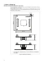
Страница 83: ...inted circuit board of the user system is designed consider the height of the parts so that components mounted to the user system and the header board do not interfere within range of the header board as shown in Figure 1 Figure 1 Header board dimensions 1 2 119 120 1 2 119 120 CN2 CN3 CN1 5 0mm 5 0mm 4 φ3 5mm 12 1mm 13 0mm 68 0mm 68 0mm The height differs slightly depending on how the YQPACK and ...

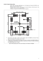
Страница 84: ...oration Figure 2 Recommended dimensions of the footprint for mounting the NQPACK 0 4mm 0 2mm 15 1mm No 1 pin φ 3 2mm 2 3 φ 1 0mm 1 15 1mm 8 0mm 2 0mm 2 0mm 2 0mm 2 0mm 0 4mm 35 14 0mm 8 0mm 0 4mm 35 14 0mm 1 The positions of the holes φ1 0mm for the guide pins when the NQPACK is mounted These holes are not needed if the guide pins are not used 2 The position of the screw hole φ3 2mm used to affix ...

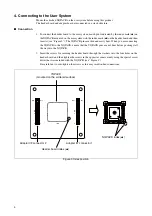
Страница 85: ...you are connecting the YQPACK to the NQPACK ensure that the YQPACK pins are not bent before pushing it all the way into the NQPACK 2 Insert the screws for securing the header board through the washers into the four holes on the header board and then tighten the screws in the opposite corners evenly using the special screw driver that was included with the NQPACK see Figure 4 Be careful not to over...

Страница 86: ...crews and then pull the head er board straight out of the socket 5 Connecting to an Adapter Board For information about how to connect the header board to the adapter board refer to the operation manual for the adapter board from the NQPACK Screws for securing header board Washer YQPACK NQPACK Header board User system ...

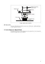
Страница 87: ...o the NQPACK see Figure 5 The HQPACK pins are thin and easily bent When you are connecting the HQPACK to the NQ PACK ensure that the HQPACK pins are not bent before pushing it all the way into the NQ PACK 3 Insert the screws for securing the HQPACK into the four holes in the HQPACK and then tighten the screws in the opposite corners evenly using the special screw driver that was included with the ...

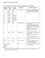
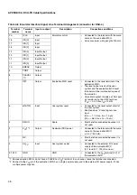
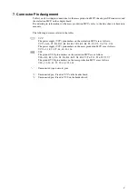
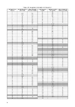
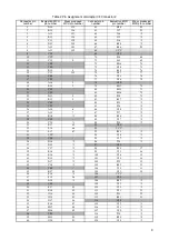
Страница 88: ...s on the evaluation MCU are as follows VCC A18 C3 D8 D12 E1 K1 K17 R1 R3 R6 T8 U2 U5 V6 V14 V18 The power supply VCC pin numbers on the mass production MCU are as follows VCC 1 18 35 37 44 60 81 126 VSS The ground VSS pin numbers on the evaluation MCU are as follows VSS B8 B12 C16 D1 D4 K4 K15 N2 R8 T3 T6 T12 T16 V1 V3 V7 The ground VSS pin numbers on the mass production MCU are as follows VSS 19 ...

Страница 89: ...6 119 79 VSS 20 A4 118 80 M2 50 21 D6 117 81 M4 51 22 VSS 82 M3 52 23 VCC 83 VSS 24 C6 116 84 VSS 25 B5 115 85 P1 34 26 A3 114 86 VSS 27 B4 113 87 VSS 28 D5 112 88 VCC 29 C5 111 89 VCC 30 A2 110 90 VSS 31 B3 109 91 VCC 32 VSS 92 VSS 33 VSS 93 T4 38 34 C4 54 94 U3 39 35 A1 53 95 V2 40 36 VSS 96 T5 41 37 VSS 97 R5 42 38 B2 97 98 U4 43 39 D3 98 99 VCC 40 C2 99 100 VSS 41 B1 100 101 VSS 42 E3 101 102 ...

Страница 90: ... VSS 80 M15 73 21 VSS 81 M16 72 22 D13 4 82 P18 75 23 B13 5 83 R17 2 24 VSS 84 P15 2 25 VSS 85 P16 2 26 A14 6 86 U18 2 27 A15 7 87 T17 2 28 B16 1 88 R16 2 29 VSS 89 U17 2 30 C15 1 90 T15 2 31 B17 65 91 VSS 32 L18 66 92 VCC 33 L17 67 93 R15 2 34 VCC 94 U16 2 35 VSS 95 V17 2 36 D16 2 96 T14 2 37 D15 2 97 VSS 38 C17 2 98 R14 17 39 B18 2 99 U15 16 40 E16 2 100 V16 15 41 E15 2 101 U14 14 42 D17 2 102 T...

Страница 91: ...TSU MICROELECTRONICS SUPPORT SYSTEM DSU FR EMULATOR LQFP 144P HEADER TYPE 9 MB2198 161 E OPERATION MANUAL April 2008 the first edition Published FUJITSU MICROELECTRONICS LIMITED Edited Strategic Business Development Dept ...

Страница 92: ......
Страница 93: ...FR Family MB2198 01 Emulating and Debugging Installation Guide Doc No 002 05223 Rev A Cypress Semiconductor 198 Champion Court San Jose CA 95134 1709 http www cypress com ...

Страница 94: ...eign United States copyright laws and international treaty provisions Cypress hereby grants to licensee a personal non exclusive non transferable license to copy use modify create derivative works of and compile the Cypress Source Code and derivative works for the sole purpose of creating custom software and or firmware in support of licensee product to be used only in conjunction with a Cypress i...

Страница 95: ... 3 5 Reset MCU 11 4 Breakpoints and Program Stepping 12 4 1 Setting Break Points 12 4 2 Using a Break Point 12 5 Monitoring and Manipulating 16 5 1 Monitoring and Manipulating Processor Status 16 5 2 Monitoring and Manipulating CPU Registers 16 5 3 Monitoring and Manipulating C Variables 17 5 3 1 Example of Manipulating Variables 18 5 4 Monitoring and Manipulating Memory 18 5 4 1 Example of Manipu...

Страница 96: ...oc No 002 05223 Rev A 4 7 Time Measurement 24 7 1 Setup Time Measurement 24 8 Event 25 8 1 Setup Sequence function 25 9 Trigger Input and Emulator Output 27 9 1 The BNC Connectors 27 9 2 Trigger Input 28 9 3 Emulator Output 28 Revision History 29 Document Revision History 29 ...

Страница 97: ...rmation please refer to the following manuals MB2198 01 Hardware Manual Emulator MB2198 01 Getting Started Application Note AN FMEMCU 910027 MB2198 01 Installation Guide Application Note AN FMEMCU 910026 This document describes the debugging methods of a MB91V230 FR 60 Lite System together with a Starterkit MB91230 Board Please note that the debugging principle is the same for other evaluation sys...

Страница 98: ...re MB91V230 copy the template project of the Softune samples into an own folder and start the Softune Workbench Software Please note that all examples are for demonstration purpose only Cypress is not taking over responsibility for any reliability 2 2 Main c The following sample code program based on the standard template project is used for demonstrating emulation and debugging Please change Main...

Страница 99: ...uses the global variables i for counting The main program void main set the LED port of the Starterkit MB91230 to output and low level After this and endless loop ist startet In this loop a call to the wait function is performed and the LED port register is increased By executing this small program the LEDs of the board are flashing The left ones faster the right ones in a lower fequency MAIN C de...

Страница 100: ... selected General purpose Optimization Level None Then compile the project by clicking on selecting Project Build or pressing Ctrl F8 Watch for error messages If all is ok you will get the following message Now building Configuration Template prj Debug vectors c Startup asm MAIN C Now linking Your path Debug ABS Template abs Now starting load module converter Your path Debug ABS Template mhx No Er...

Страница 101: ... 01 AN FMEMCU 910026 and Emulator System MB2198 01 Getting started AN FMEMCU 910027 for details 3 2 Entering Debugger Mode After successful compilation of the project start the debugging mode via COM1 2 USB or LAN by double clicking on the regarding Debug sup entry in the workspace window After successful connection to the emulator open Main c close it first if it is open and then click on right m...

Страница 102: ... R12 000C01AA 14C0 ST R0 R12 000C01AC 9B3CC000 LDI 20 3C000 R12 000C01B0 04C0 LD R12 R0 000C01B2 2021 LD R14 8 R1 000C01B4 AA10 CMP R1 R0 000C01B6 E508 BNC 000C01C8 000C01B8 9B3CC000 LDI 20 3C000 R12 000C01BC 04C0 LD R12 R0 000C01BE A410 ADD 1 R0 000C01C0 9B3CC000 LDI 20 3C000 R12 000C01C4 14C0 ST R0 R12 000C01C6 E0F2 BRA 000C01AC 19 000C01C8 9F90 LEAVE 000C01CA 0781 LD R15 RP 000C01CC A301 ADDSP ...

Страница 103: ...n continuously or selecting Go 3 5 Reset MCU To reset the MCU clock on or select Debug Reset of MCU Continuation from previous page 000C01D6 8B0D MOV R0 R13 000C01D8 1A01 DMOVB R13 001 24 DDR1 0xFF 000C01DA CFF0 LDI 8 FF R0 000C01DC 9B0C0401 LDI 20 00401 R12 000C01E0 16C0 STB R0 R12 25 26 while 1 27 28 wait 20000 000C01E2 9B044E20 LDI 20 04E20 R4 000C01E6 D7DB CALL wait 29 30 PDR1 000C01E8 0A01 DM...

Страница 104: ... circle The symbol then turns to 4 2 Using a Break Point Assume you want to examine the program in the example above A good breakpoint would be just before calling the wait function Therefore set the breakpoint to Address H 000C01E2 Now start execution press F5 25 26 while 1 27 28 wait 20000 X 000C01E2 9B044E20 LDI 20 04E20 R4 000C01E6 D7DB CALL wait 29 30 PDR1 000C01E8 0A01 DMOVB 001 R13 000C01EA...

Страница 105: ...n and is waiting at the call instruction to the subroutine at H 000C01E6 Do one instruction step further press F6 Then the highlighted line will jump to the wait function 25 26 while 1 27 28 wait 20000 X 000C01E2 9B044E20 LDI 20 04E20 R4 000C01E6 D7DB CALL wait 29 30 PDR1 000C01E8 0A01 DMOVB 001 R13 000C01EA 8BD0 MOV R13 R0 000C01EC A410 ADD 1 R0 000C01EE 8B0D MOV R0 R13 000C01F0 1A01 DMOVB R13 00...

Страница 106: ...p over command Debug Run Step Over or F7 With the Execute until cursor position command Debug Run Run Until Cursor or Ctrl F7 you can set a temporary breakpoint Therefore click into the source window so that the cursor is flashing Then reset the CPU and perform the command The execution will stop at the cursor position Note that the execution only stops if the marked program code is executed Be ca...

Страница 107: ... to a specified memory location by directly clicking at the address When turning the mouse pointer over the left side of the mix display window the pointer turns to Clicking then sets a temporary break point This means that the code is executed until the marked address is reached Note that this only works if this code line is ever reached ...

Страница 108: ...ame S Stack flag 0 User stack 1 System stack I Interrupt enable flag 1 enable N Negative flag MSB 1 in last operation Z Zero flag Last operation resulted in 0 V Overflow flag Overflow at last operation C Carry flag Last operation caused carry The value of the flags can be easily changed by clicking into the white square A check mark indicates that the flag is set 1 5 2 Monitoring and Manipulating ...

Страница 109: ...op up window will occur and look like the following picture In the dialog frame Register value you can enter a new value for the register Note that the values always are shown in hexadecimal notation by set up default but you can enter even decimal values beginning with D binary values beginning with B or octal values beginning with O 5 3 Monitoring and Manipulating C Variables To display C variab...

Страница 110: ... several times you will note that the loop is only executed one time because the counter i has reached the count of 1 of the comparison argument a 5 4 Monitoring and Manipulating Memory To display the MCU memory choose in the debugging mode View Memory A pop up window Watch will occur and ask for the start address to be displayed Type a hexadecimal number with leading H and press RETURN A new wind...

Страница 111: ... will change immediately to H 40200000 5 4 2 Realtime Memory There is another way to view memory Choose View Realtime memory A Setup window will occur if not click the right button of the new opened window and select Setup Area In the Setup debug environment window select Realtime memory area Enter 0 for the Start address for Area number 1 Click on Set and then OK The new Realtime memory window lo...

Страница 112: ...highlighted in red Note memory manipulation is not possible in the Realtime memory window 5 5 Symbol view If you want to know where a variable is located in the memory you can choose View Symbol Then unfold the sub list Project_name abs Global Symbol Click with the right mouse button to the variable you want to get information about and select Property The Symbol sub window shows then the address ...

Страница 113: ...t this window only shows contents if the debugger is in stop mode e g breakpoint reached and the actual function has local variables To demonstrate the Local view window open Main c in mixed display and set a breakpoint at address H 000C01A4 within the sub function wait Now start execution and look at the Local view window when the CPU stops at the breakpoint The window will show the local variabl...

Страница 114: ...e mnemonic or a data transfer inclusive data value Note that the last executed frame has the number 1 and all previous frames negative numbers The time stamp shows the execution time of the instruction including all internal cycles in nano seconds billionth seconds Please also note that in this view the execution frame of the instructions is shown not their fetch frame Frame no address mnemonic 00...

Страница 115: ...01D0 R12 625 00009 000C01D0 ST RP R15 50 00008 write 000C02AE at 0003C802 25 00007 write 00000487 at 0003C7FE 275 00006 write 00 at 00000001 325 00005 write FF at 00000401 800 00004 000C019E ST R4 R15 25 00003 write 00004E20 at 0003C7FA 125 00002 write 000C01E8 at 0003C7F6 75 00001 write 0003C7FE at 0003C7F2 350 00000 16 void wait unsigned int a 000C019E 1704 ST R4 R15 000C01A0 1781 ST RP R15 000C...

Страница 116: ...e call to the wait function Now choose Debug Time Measurement You will find the following information From Initialize 0h00m00s002ms115us375ns Time Time from Reset to main 1 st breakpoint From Last Executed 0h00m000ms001us100ns Time Time to wait 1 st breakpoint to 2 nd breakpoint From Initialize 4350 Cycle see above From Last Executed 35 Cycle see above The number of measurement cycles includes an ...

Страница 117: ...et complex breakpoints or a restart condition Two kinds of conditions can be set Code The execution program counter register meets a defined address similar to usual breakpoints Data Defined data is written to or read from a defined address Conditions can be set sequentially To use the event function enter debugging mode and choose Debug Event The event window will open and look like this ...

Страница 118: ...ays click on Append in the event window when entering a new event If you forget this point Softune will not accept the entries and they will get lost Now start execution and the CPU will stop afterwards The mixed display will look like this 26 while 1 27 28 wait 20000 000C01E2 9B044E20 LDI 20 04E20 R4 000C01E6 D7DB CALL wait 29 30 PDR1 000C01E8 0A01 DMOVB 001 R13 000C01EA 8BD0 MOV R13 R0 000C01EC ...

Страница 119: ...nstallation Guide Doc No 002 05223 Rev A 27 9 Trigger Input and Emulator Output How to Use the Two BNC Connectors 9 1 The BNC Connectors The MB2198 01 emulator has two BNC connectors The left one is the Trig Input and the right one the Emul Output ...

Страница 120: ...range of dozens to hundreds machine clock cycles The execution can be resumed after a triggered break Because of the 3 3V input and an internal 100K pull down resistor it is recommended to use a serial 50K resistor if a 5V signal is used 9 3 Emulator Output The BNC Output EMUL goes logical high 3 3V if a program is executed and is low 0V if the program is stopped or a break point has occurred This...

Страница 121: ... Document Revision History Document Title FR Family MB2198 01 Emulating and Debugging Installation Guide Document Number 002 05223 Revision Issue Date Origin of Change Description of Change 05 27 2004 NOFL Initial release A 03 22 2016 NOFL Migrated Spansion guide from MCU AN 391028 E V10 to Cypress format ...

Отзывы: