7
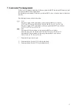
7. Connector Pin Assignment
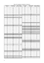
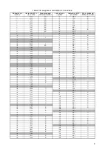
Tables 1 and 2 list the pin connections for the mass production MCU, the adapter I/F connectors, and
the evaluation MCU on the adapter board.
For detailed pin information for the mass production MCUs, refer to the data sheets or hardware
manuals.
The following notes are related to the tables.
: VCC
The power supply (VCC) pin numbers on the evaluation MCU are as follows.
VCC = A18, C3, D8, D12, E1, K1, K17, R1, R3, R6, T8, U2, U5, V6, V14, V18
The power supply (VCC) pin numbers on the mass production MCU are as follows.
VCC = 1, 18, 35, 37, 44, 60, 81, 126
: VSS
The ground (VSS) pin numbers on the evaluation MCU are as follows.
VSS = B8, B12, C16, D1, D4, K4, K15, N2, R8, T3, T6, T12, T16,V1,V3,V7
The ground (VSS) pin numbers on the mass production MCU are as follows.
VSS = 19, 36, 45, 55, 59, 80, 125, 144
“ - ” : Unconnected (open circuit) pins
*1 : Unconnected pin : Fixed to VCC on the header board.
*2 : Unconnected pin : Fixed to VSS on the header board.
Содержание MB2147-01
Страница 9: ...FUJITSU SEMICONDUCTOR CONTROLLER MANUAL DSU FR EMULATOR MB2198 01 HARDWARE MANUAL CM71 00413 2E ...
Страница 10: ......
Страница 11: ...FUJITSU LIMITED DSU FR EMULATOR MB2198 01 HARDWARE MANUAL ...
Страница 12: ......
Страница 20: ...viii ...
Страница 22: ...x ...
Страница 56: ...34 CHAPTER 2 CONNECTION METHOD ...
Страница 64: ...42 CHAPTER 3 OPERATION METHOD ...
Страница 66: ......
Страница 69: ...47 APPENDIX A DSU FR Cable Specifications Figure A 2 Connector Terminal Arrangement for DSU 3 Pin 1 Pin 30 ...
Страница 76: ...54 APPENDIX B User System Specifications ...
Страница 78: ......
Страница 92: ......

