9
1.7 External Trigger Input Terminal Specifications
1.7
External Trigger Input Terminal Specifications
The emulator has the TRIG terminal that is used as a input terminal for external trigger
signals.
■
External Trigger Input Terminal Specifications
The external trigger input terminal is a part that connects a logic analyzer or other such external
device to the emulator. An external device uses the external trigger input terminal to request the
evaluation MCU on the user system for a break (External trigger break function).
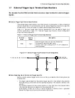
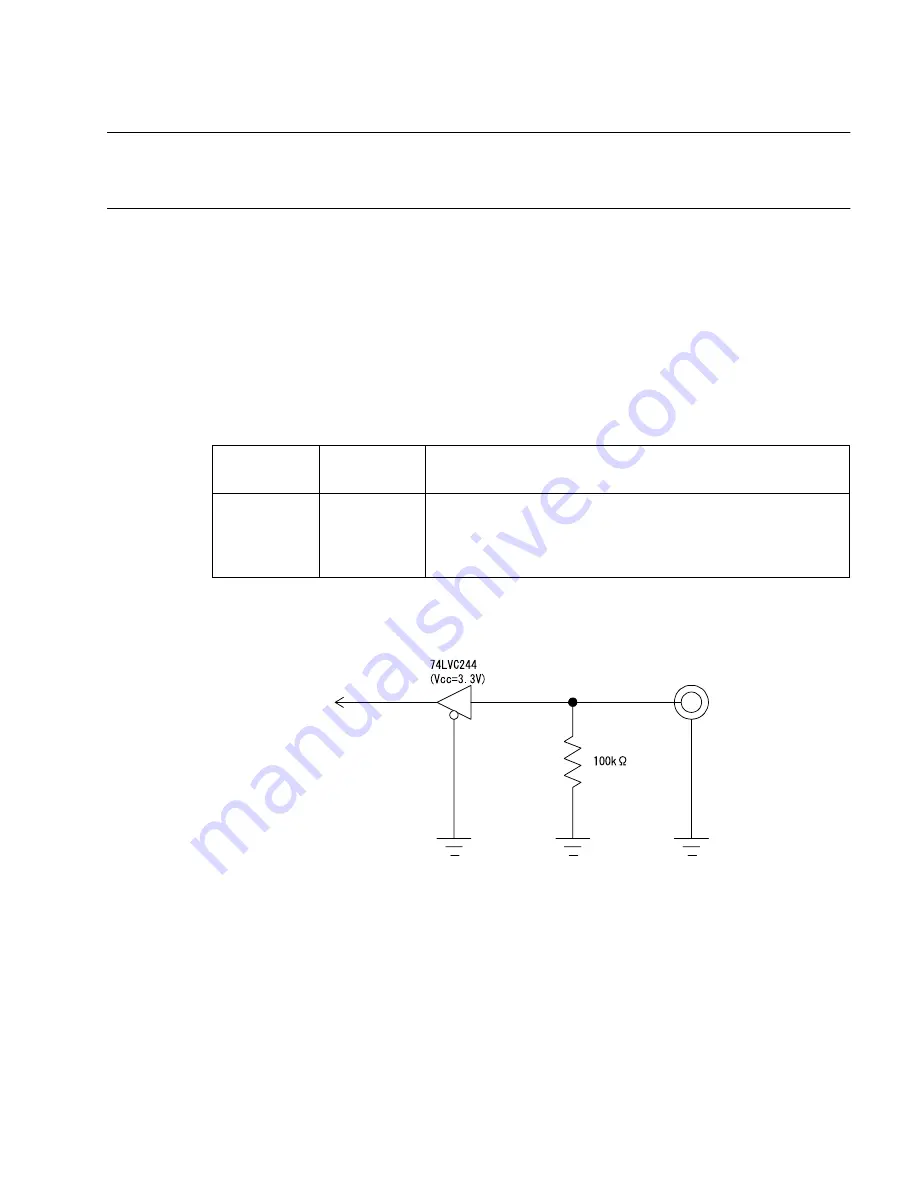
Table 1.7-1 "External Trigger Input Terminal Specifications" lists the external trigger input
terminal specifications. Figure 1.7-1 "External Trigger Input Terminal Circuit Configuration"
shows the circuit configuration.
Figure 1.7-1 External Trigger Input Terminal Circuit Configuration
■
Notes Regarding Use of the External Trigger Input Pin
Before using the external trigger function, be sure that you understand the following break slip
characteristics:
•
The trigger signal entered from the external trigger input pin is transmitted to the evaluation
MCU after being synchronized with the operating frequency of the emulator interface in the
emulator.
The operating frequency of the emulator interface is lower than that of the evaluation MCU
(The operating frequency ratio depends on the evaluation MCU.).
Consequently, a break slip of tens to several hundreds of machine clocks is generated
between the trigger signal input and the evaluation MCU break.
Table 1.7-1 External Trigger Input Terminal Specifications
Terminal
name
Input or
output
Description
TRIG
Input
External trigger signals are input into this terminal.
The terminal is used for break control.
A break occurs when a change from "L" to "H" is detected in
input signal level.
To internal circuits of emulator
TRIG terminal
(BNC connector)
Содержание MB2147-01
Страница 9: ...FUJITSU SEMICONDUCTOR CONTROLLER MANUAL DSU FR EMULATOR MB2198 01 HARDWARE MANUAL CM71 00413 2E ...
Страница 10: ......
Страница 11: ...FUJITSU LIMITED DSU FR EMULATOR MB2198 01 HARDWARE MANUAL ...
Страница 12: ......
Страница 20: ...viii ...
Страница 22: ...x ...
Страница 56: ...34 CHAPTER 2 CONNECTION METHOD ...
Страница 64: ...42 CHAPTER 3 OPERATION METHOD ...
Страница 66: ......
Страница 69: ...47 APPENDIX A DSU FR Cable Specifications Figure A 2 Connector Terminal Arrangement for DSU 3 Pin 1 Pin 30 ...
Страница 76: ...54 APPENDIX B User System Specifications ...
Страница 78: ......
Страница 92: ......


