Monitoring and Manipulating
FR Family MB2198-01 Emulating and Debugging Installation Guide, Doc. No. 002-05223 Rev. *A
19
5.4.1
Example of Manipulating Memory
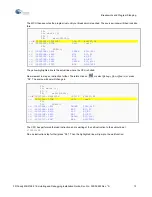
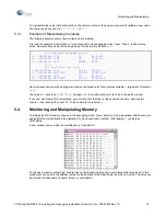
Use the example program from above compile it and enter debugging mode.
Set a break point at address
H’000C01A4
:
Enter execution mode and the CPU stops at
H’000C01A4
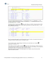
. Now select
View
Watch
and add variable
a
. Then
select
View
Memory
and enter start address
H’3C7FA
.
You will find the C variable
a
at the address
H’0003C7FA
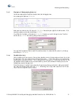
. Assume you want to change its value. Therefore
double click on
H’3C7FA
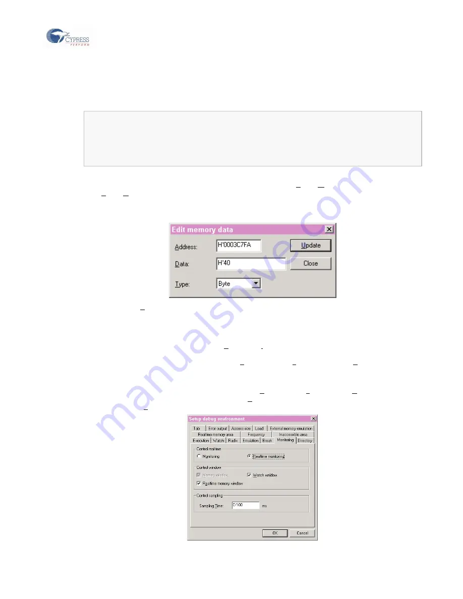
. The following dialog window will pop up:
Now type
40
in the
Data
text field and watch the variable window. You will see that the value of
a
will change
immediately to
H’40200000
.
5.4.2
Realtime Memory
There is another way to view memory. Choose
View
Realtime memory
. A Setup window will occur (if not, click
the right button of the new opened window and select
Setup Area…
.). In the
Setup debug environment
window
select
Realtime memory
area
. Enter “
0
” for the
Start address
for
Area number: 1
. Click on
Set
and then
OK
. The
new Realtime memory window looks much like the Memory window, but is limited to 255 Byte (per area), but
highlights any memory changes in red.
To see the memory in “real time” during execution, choose
Setup
Debug environment
Debug environment
.
Then select the
Monitoring
folder and enter “
D’100
at
Sampling Time:
(using USB connection to the PC) and
click on check box
Realtime memory window
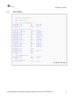
:
=>
(
)
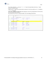
000C01A0: 1781 ST RP,@-R15
=>
(
)
000C01A2: 0F01 ENTER #004
17: {
18: for (i=0; i<a; i++);
=>
(
X
)
000C01A4: C000 LDI:8 #00,R0
=>
(
)
000C01A6: 9B3CC000 LDI:20 #3C000,R12
Содержание MB2147-01
Страница 9: ...FUJITSU SEMICONDUCTOR CONTROLLER MANUAL DSU FR EMULATOR MB2198 01 HARDWARE MANUAL CM71 00413 2E ...
Страница 10: ......
Страница 11: ...FUJITSU LIMITED DSU FR EMULATOR MB2198 01 HARDWARE MANUAL ...
Страница 12: ......
Страница 20: ...viii ...
Страница 22: ...x ...
Страница 56: ...34 CHAPTER 2 CONNECTION METHOD ...
Страница 64: ...42 CHAPTER 3 OPERATION METHOD ...
Страница 66: ......
Страница 69: ...47 APPENDIX A DSU FR Cable Specifications Figure A 2 Connector Terminal Arrangement for DSU 3 Pin 1 Pin 30 ...
Страница 76: ...54 APPENDIX B User System Specifications ...
Страница 78: ......
Страница 92: ......

