


5-4
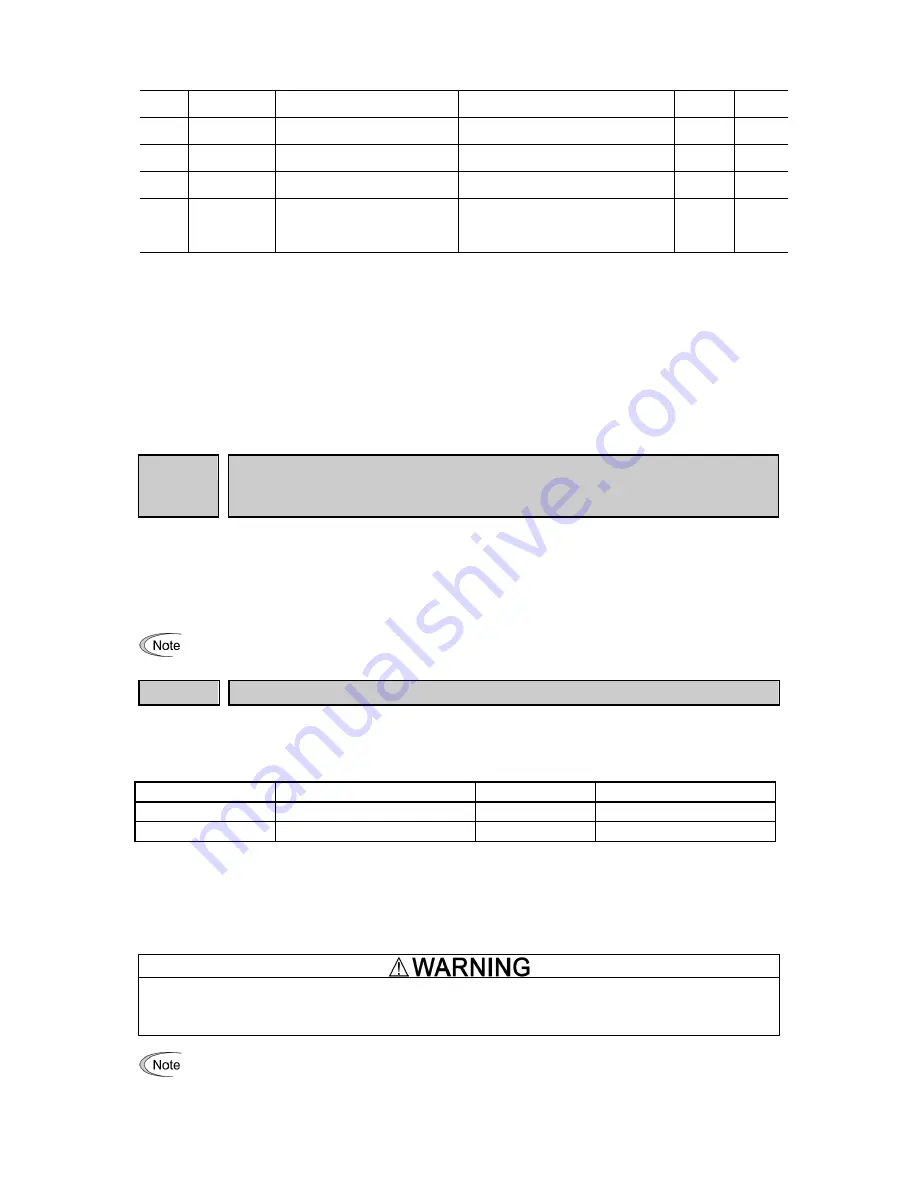
Code
Keypad code
Name
Data setting range
Factory
default
Setting
UH53
U194 (U190=151) Big step DOWN detection (Level to
detect big step DOWN)
0.00 to 100.0%
100%=500V (-2/-7), 1000V (-4)
3
3
UH83
U194 (U190=157) Big step DOWN detection (Time delay to
follow the step DOWN)
0.00 to 10.0 s (recommended range)
4.0
4.0
UH88
U194 (U190=158) Big step DOWN detection (Time to
follow the step DOWN change)
0.00 to 4.0 s (recommended range)
1.0
1.0
U00
U00
Customizable logic
(Mode selection)
0: Disable
1: Enable (Customizable logic operation)
ECL alarm occurs when the value is changed
from 1 to 0 during operation.
0
1
(Note 7): Depends on motor capacity
(Note 1): Depends on the application
(Note 2): Please set U190 to the number inside the brackets prior to changing this function
(Note 3): The motor rated current is automatically set. Refer to Table B (function code P03)
(Note 4): 5.0min for inverters of nominal applied motor 22kW or below; 10.0min for those of 30kW or above
(Note 5): For solar pumping application recommended setting is 0 or 1
(Note 6): For solar pumping application recommended modes are HND or HHD
5.2 Description of Function Codes
This section describes details of function codes relevant for Solar Pumping application.
F02
Operation method
Related function codes:
Terminal E98 [FWD] function
Terminal E99 [REV] function
F02 is used to select the method how run command is provided to the inverter. In case of Solar pumping
application please set F02 to 1, so that the operation command can be given from Customized Logic program.
Digital input signal, "FWD", "REV" should not be assigned to terminals [FWD], [REV], therefore please assign the
function of these terminals to “No function”.
(
Function code E98, E99 data = 100)
• F02 cannot be changed when "FWD" or "REV" is ON.
F03
Maximum frequency 1
F03 specifies the maximum frequency that the inverter outputs. When the device to be driven is set to rated or
higher, the device may be damaged. Make sure to make an adjustment according to the design of the machinery.
• Data setting range: 25.0 to 500.0 (Hz)
Modes
Control mode
Data setting range
Remarks
HD/HND/HHD mode
V/f control
500 Hz
ND mode
V/f control
120 Hz
Restricted internally.*
* When setting is performed by exceeding the maximum setting range (for example, 500 Hz), speed setting and
analog output (FMA) become input/output mode of full scale/setting value (10V/ 500Hz). However, it is internally
restricted (for example, 120Hz), therefore, even if 10V is input for setting value, the value is restricted internally
by 2.4 V (equivalent to 120 Hz), not by 500Hz.
Use function code F80 to switch between ND, HD, HND and HHD drive modes.
Inverter can perform setting of high speed operation easily. When changing the setting, make sure to check the
motor and machine mode before use.
Injuries could occur
.
Failure may occur.
When changing maximum output frequency (F03), in order to make the operation frequency a larger
value, change the frequency limiter (upper limit) (F15) as well.
Содержание Frenic-Sce
Страница 10: ......


