


PG9602™ OPERATION AND MAINTENANCE MANUAL
© 2011 Fluke Calibration
Page
120
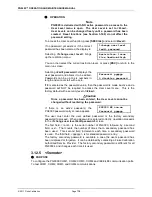
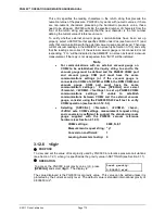
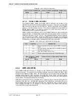
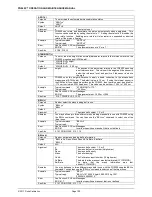
Table 19.
COM1 DB-9F Pin Designation
IBM PC/XT DB-9F CONNECTIONS
IBM PC/XT DB-9M to PG9000 DB9F CONNECTIONS
DB-25M
DB-9F
DB-9M
DB-9F
2
3
3
3
3
2
2
2
7
5
5
5
4.2.1.2
COM2, COM3 and COM4
The PG9000 COM2, COM3 and COM4 RS232 interfaces are located on the
PG9000 Remote Electronics Module (REM) rear panel. They are 9-pin male DB-
9M connectors configured as a DTE device. Data is transmitted out of PG9000
using pin 3 and is received on pin 2. This allows a standard pin-to-pin DB-9F to
DB-9M RS232 cable to be used to connect to a DCE slave (see Table 20).
Handshaking is NOT required or supported.
COM2, COM3 and COM4 are used by the PG9000 Platform to communicate with
external devices. An external barometer and/or vacuum gauge can be connected to
COM2 (see Sections 3.12.5.4, 3.12.5.5. An automated pressure control component
can be connected to COM3. Almost any RS232 device that uses text commands
and a <CR> or <CR><LF> terminator can be connected to COM4 using the PG9000
“PASSTHRU” command to pass commands from the host to the device.
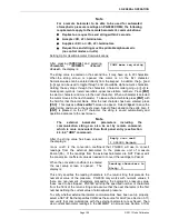
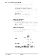
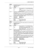
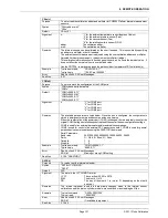
Table 20.
COM2, COM3 and COM4 DB-9M Pin Designation
PIN #
FUNCTION
DESCRIPTION
2
RxD
This pin accepts serial data from another PG9000 or another
device.
3
TxD
This pin transmits serial data from the PG9000 to another
PG9000 or another device.
4
DTR
Data Terminal Ready. Held at 5 Volts.
5
Grn
This pin is the common return for the TxD and RxD signals.
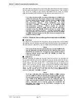
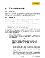
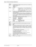
IBM PC/XT DB-25F to DB-9M
CONNECTIONS
IBM PC/XT DB-9F to PG9000 DB9M CONNECTIONS
DB-25F
DB-9M
DB-9F
DB-9M
2
3
3
3
3
2
2
2
7
5
5
5
4.2.2
IEEE-488 (GPIB)
The PG9000 IEEE-488 interface is located on the PG9000 Remote Electronics Module
(REM) rear panel. The physical and electrical interface conforms to IEEE Std 488.1-1987
Subset E2 and IEEE Std. 488.2-1992. Do NOT attempt to communicate with the IEEE-488
interface while using the COM1 interface. The IEEE-488 receive buffer is 250 bytes deep.
PG9000 will hold OFF release of the NRFD handshake line until it can service and empty the
receive buffer. This keeps the buffer from overflowing.
IEEE-488 commands must be terminated with a single line feed character along with the
assertion of the EOI line. All IEEE-488 responses from PG9000 are terminated with a line
feed character along with the assertion of the EOI line. Replies are held in a buffer until the
host computer gets them, so it is possible to have old replies in this buffer while expecting
new replies from a just issued command.
Содержание PG9000 Series
Страница 10: ...PG9602 OPERATION AND MAINTENANCE MANUAL 2011 Fluke Calibration Page X Notes...
Страница 128: ...PG9602 OPERATION AND MAINTENANCE MANUAL 2011 Fluke Calibration Page 118 Notes...
Страница 164: ...PG9602 OPERATION AND MAINTENANCE MANUAL 2011 Fluke Calibration Page 154 Notes...
Страница 188: ...PG9602 OPERATION AND MAINTENANCE MANUAL 2011 Fluke Calibration Page 178 Notes...
Страница 192: ...PG9602 OPERATION AND MAINTENANCE MANUAL 2011 Fluke Calibration Page 182 Notes...


