Preparing for Operation
Instrument Preparation
2
2-7
XW
Warning
To avoid shock hazard when powering the instrument with
dc power, connect the instrument ground terminal to an
earth ground.
Operating Using DC Power
The instrument operates from any dc voltage between 9 and 45 V. Power
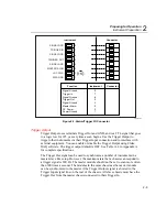
consumption is a nominal 30 watts. To connect the POWER/ALARM/TRIGGER
connector to the rear panel, complete the following procedure:
1.
Remove the POWER/ALARM/TRIGGER connector from the packing
material or instrument rear panel.
2.
Loosen the wire clamp screw for the associated terminal.
3.
Feed the wire into the gap between the connector body and the wire clamp.
4.
Tighten the wire clamp; do not over tighten and crush the wire.
5.
Repeat steps 2 through 4 for each wire.
6.
Insert the connector in the rear panel.
Note
A 4 amp fuse is used to protect the dc input from over current. This
fuse is located inside the 2680 Series chassis on the main controller
board. The fuse should only be replaced by a Fluke qualified
technician with all power disconnected from the instrument.
Grounding and Common Mode Voltage
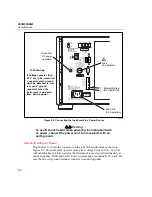
Connect the instrument chassis to a good earth ground (Figure 2-2) to prevent a
common mode voltage from raising the chassis to a high potential. For example, if
you measure the voltage across a resistor in a 50 V dc circuit, the instrument reads
the resistor voltage and ignores the 50 V dc common mode voltage. Since the
impedance between the channel inputs and chassis ground is not infinite, a
common mode voltage gradually leaks to the chassis ground. A good earth ground
prevents the chassis from rising to the common-mode voltage (50 V dc in this
case).
Alarm/Trigger I/O Connection
XW
Caution
To avoid damage to the instrument, do not apply any
voltages greater than 30 V maximum between the
ALARM/TRIGGER I/O connector terminals and signal
ground.
Содержание 2680A
Страница 8: ......
Страница 14: ...2680A 2686A Users Manual vi ...
Страница 20: ...2680A 2686A Users Manual 1 2 ...
Страница 98: ...2680A 2686A Users Manual 2 62 ...
Страница 196: ......
Страница 228: ...2680A 2686A Users Manual A 32 ...
Страница 236: ...2680A 2686A Users Manual C 4 ...
Страница 242: ...2680A 2686A Users Manual D 6 ...
Страница 274: ...2680A 2686A Users Manual 6 ...


