Maintenance
DC Fuse Replacement
4
4-9
DC Fuse Replacement
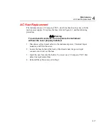
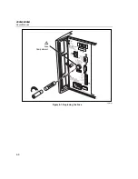
The 2680A/2686A instruments use a 4 ampere, 125 V, slow blow fuse in series
with the dc supply “+” input. This fuse is mounted on the main controller board
inside the chassis. Because of potential high voltages, this fuse should only be
replaced by a Fluke qualified technician. :
XW
Warning
The 2680 Series chassis contains high voltages that can
be dangerous or fatal. Only qualified personnel should
attempt to service the chassis.
Performance Test
When shipped, the 2680A/2686A is calibrated and in operating condition. The
following performance test procedures are provided for acceptance testing upon
initial receipt or to verify correct instrument operation. The performance tests must
be performed in sequence.
If the instrument fails a performance test, the instrument requires service or repair.
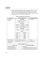
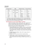
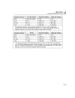
To perform these tests, you will need a Fluke 5700A Multifunction Calibrator and
several other pieces of equipment meeting the minimum specifications given in
Table 4-2.
Each of the measurements listed in the following steps assume the instrument is
being tested after a one hour warm-up, in an environment with an ambient
temperature of 18 to 28 °C, and a relative humidity of less than 70%.
Some of the digital tests can be run either through the RS-232 port or by using
Fluke DAQ software. With most procedures, you can use either method to verify
functionality. For the RS-232 tests, you will also need to use a program such as
HyperTerminal to perform the test. See Appendix J for a complete listing of the
RS-232 commands.
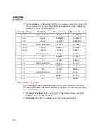
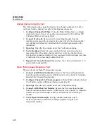
Configuring the Performance Test Setup
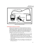
Configure the performance test setup as described below. The performance test
requires a complete network connection between the host computer and 2680
Series under test, including a host computer Ethernet interface and installation of
the Fluke DAQ software. If you have not yet configured and tested a network
connection for the host computer and instrument, complete the appropriate
installation procedure for your network configuration before conducting any
performance testing.
1.
Connect the Instrument and the Host Computer
Connect the supplied
Ethernet cross connect cable between the host computer Ethernet port and the
2680 Series Ethernet port.
Содержание 2680A
Страница 8: ......
Страница 14: ...2680A 2686A Users Manual vi ...
Страница 20: ...2680A 2686A Users Manual 1 2 ...
Страница 98: ...2680A 2686A Users Manual 2 62 ...
Страница 196: ......
Страница 228: ...2680A 2686A Users Manual A 32 ...
Страница 236: ...2680A 2686A Users Manual C 4 ...
Страница 242: ...2680A 2686A Users Manual D 6 ...
Страница 274: ...2680A 2686A Users Manual 6 ...

