321023
98
7. Remove and replace restricted device.
8. Evacuate sealed system.
9. Charge system to specification.
NOTE:
Do not use captured or recycled refrigerant in units. Captured or recycled refrigerant voids
any compressor manufacturer's warranty.
NOTE:
Charge system with exact amount of refrigerant. Refer to unit serial plate for correct
refrigerant charge. Inaccurately charged system will cause future problems.
13.10
Evacuation and Charging
13.10.1 Evacuation
CAUTION
To avoid risk of fire, sealed refrigeration system must be air free. To avoid risk of air
contamination, follow evacuation procedures exactly.
NOTE:
Before opening any refrigeration system, EPA regulations require refrigerant in system to be
captured for safe disposal.
Proper evacuation of sealed refrigeration system is an important service proc edure. Usable
life and operational efficiency greatly depends upon how completely air, moisture and other non-
condensables are evacuated from sealed system.
Air in sealed system causes high condensing temperature and pressure, resulting in increased power
requirements and reduced performance.
Moisture in sealed system chemically reacts with refrigerant and oil to form corrosive hydrofluoric and
hydrochloric acids. These acids attack motor windings and parts, causing premature breakdown.
Before opening system, evaporator coil must be at ambient temperature to minimize moisture
infiltration into system.
Evacuation
To evacuate sealed refrigeration system:
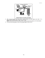
1. Connect vacuum pump, vacuum tight manifold set with high vacuum hoses, thermocouple vacuum
gauge and charging cylinder as shown in illustration.
Evacuation should be done through I.D. opening of tubes, not through line piercing valve.
2. Connect low side line to compressor process tube.
3. Connect high side line to drier/process tube.
4. Evacuate both simultaneously. With valve “C” and “F” closed, open all other valves and start
vacuum pump.
Содержание RX256DT4X1
Страница 11: ...321023 11 2 3 Refrigerant Flow...
Страница 12: ...321023 12 2 4 Cabinet Air Flow...
Страница 13: ...321023 13 2 5 Ice And Water Dispenser Diagram...
Страница 14: ...321023 14 2 6 Water Valve Diagram...
Страница 15: ...321023 15 2 7 Typical External Sweat Pattern...
Страница 16: ...321023 16 3 INSTALLATION...
Страница 17: ...321023 17...
Страница 18: ...321023 18...
Страница 76: ...321023 76 Ice Water Dispensing Board...
Страница 78: ...321023 78 Mid Electronic Specification Control RX256DT4X1 RX256ET2B1 RX256ET2W1...
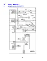
Страница 104: ...321023 104 14 WIRING DIAGRAMS 14 1 Wiring Schematic RX256DT7X1...
Страница 105: ...321023 105 14 2 Wiring Diagram RX256DT7X1...
Страница 106: ...321023 106 14 3 Wiring Schematic RX256DT4X1 RX256ET2B1 RX256ET2W1...
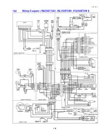
Страница 107: ...321023 107 14 4 Wiring Diagram RX256DT4X1 RX256ET2B1 RX256ET2W1...
Страница 108: ...321023 108 NOTES...


