321023
31
Component Description
Test
Procedures
Evaporator
Inner volume of evaporator
allows liquid refrigerant
discharged from capillary to
expand into refrigerant gas.
Expansion cools evaporator
tube and fin temperature to
approximately –20
O
F,
transferring heat from freezer
section to refrigerant.
Passing through suction line to
compressor, the refrigerant
picks up superheat (a
relationship between pressure
and temperature that assures
complete vaporization of liquid
refrigerant) as the result of
capillary tube soldered to
suction line.
Refrigerant gas is pulled
through suction line by
compressor, completing
refrigeration cycle.
Test for leaks in evaporator with electronic leak detector or
with leak detection fluid.
Compressor oil is circulated with refrigerant; check for oil when
checking for leaks.
For minute leaks
1. Separate evaporator from rest of refrigeration system and
pressurize evaporator up to a maximum of 140 PSI with a
refrigerant and dry nitrogen combination.
2. Recheck for leaks.
WARNING
To avoid personal injury or death from sudden eruption of
high pressure gases, observe the following:
Protect against a sudden eruption if high pressures are
required for leak checking.
Do not use high pressure compressed gases in
refrigeration systems without a reliable pressure
regulator and pressure relief valve in the lines.
Evaporator defrost
heater
Activated when defrost
thermostat, defrost timer, and
freezer control complete circuit
through heater.
Check resistance across heater.
To check defrost system:
1. Thermocouple defrost thermostat and plug refrigerator into
wattmeter.
2. Turn into Forced Defrost Mode. Wattmeter should read
specified watts (according to Technical Data Sheet).
3. When defrost thermostat reaches specified temperature
±5
O
F (see Technical Data Sheet), thermostat should
interrupt power to heater.
Thermostat
Thermostat is in a series circuit
with terminal 2 of defrost timer,
and defrost heater. Circuit is
complete if evaporator fan motor
operates when cold.
Controls the circuit from freezer
thermostat through defrost
terminator to defrost heater.
Opens and breaks circuit when
thermostat senses preset high
temperature.
Test continuity across terminals.
With power off and evaporator coil below freezing, thermostat
should show continuity when checked with ohmmeter. See
“Heater, evaporator (defrost)” section for additional tests.
After defrost thermostat opens, thermostat remains open until
end of defrost cycle and refrigerator starts cooling again.
Defrost thermostat senses a preset low temperature and
resets (closes).
Thermistor
Temperature sensing device.
Check resistance across leads.
Temperature Resistance
77
O
F / 25
O
C 10,000
ohms
36
O
F / 2
O
C 29,500
ohms
0
O
F / -18
O
C 86,300
ohms
Ice & water
dispensing board
Customer water and ice
dispensing interface board.
Refer to specific the Technical Data Sheet supplied with the
unit for troubleshooting procedures.
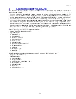
Electronic control
board
Customer fresh food
compartment and freezer
temperature adjustment
interface board.
Refer to specific the Technical Data Sheet supplied with the
unit for troubleshooting procedures.
Содержание RX256DT4X1
Страница 11: ...321023 11 2 3 Refrigerant Flow...
Страница 12: ...321023 12 2 4 Cabinet Air Flow...
Страница 13: ...321023 13 2 5 Ice And Water Dispenser Diagram...
Страница 14: ...321023 14 2 6 Water Valve Diagram...
Страница 15: ...321023 15 2 7 Typical External Sweat Pattern...
Страница 16: ...321023 16 3 INSTALLATION...
Страница 17: ...321023 17...
Страница 18: ...321023 18...
Страница 76: ...321023 76 Ice Water Dispensing Board...
Страница 78: ...321023 78 Mid Electronic Specification Control RX256DT4X1 RX256ET2B1 RX256ET2W1...
Страница 104: ...321023 104 14 WIRING DIAGRAMS 14 1 Wiring Schematic RX256DT7X1...
Страница 105: ...321023 105 14 2 Wiring Diagram RX256DT7X1...
Страница 106: ...321023 106 14 3 Wiring Schematic RX256DT4X1 RX256ET2B1 RX256ET2W1...
Страница 107: ...321023 107 14 4 Wiring Diagram RX256DT4X1 RX256ET2B1 RX256ET2W1...
Страница 108: ...321023 108 NOTES...

