background image

321023 

97 

13.9 Restrictions 

13.9.1 Symptoms 

Restrictions in sealed system most often occur at capillary tube or filter drier, but can exist anywhere 
on liquid side of system. 
 
Restrictions reduce refrigerant flow rate and heat removal rate.  Wattage drops because compressor 
is not circulating normal amount of refrigerants. 
 
Common causes of total restrictions are moisture, poorly soldered joints, or solid contaminants.  
Moisture freezes at evaporator inlet end of capillary tube.  Solid contaminants collect in filter drier. 
 
If restriction is on low side, suction pressure will be in a vacuum and head pressure will be near 
normal. 
 
If restriction is on high side, suction pressure will be in a vacuum and head pressure will be 
higher than normal during pump out cycle. 
 
Refrigeration occurs on low-pressure side of partial restriction.  There will be a temperature 
difference at the point of restriction.  Frost and/or condensation will be present in most case at the 
point of restriction.  Also, system requires longer to equalize. 
 
Slight or partial restriction can give the same symptoms as refrigerant shortage, including lower than 
normal backpressure, head pressure, wattage, and warmer temperatures. 
 
Total restriction on the discharge side of compressor, when restriction is between compressor and 
first half of condenser, results in higher than normal head pressure and wattage while low side is 
being pumped out. 

13.9.2 

Testing for Restrictions 

To determine if a restriction exists: 
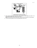
1.  Attach gauge and manifold between suction and discharge sides of sealed system. 
2.  Turn unit on and allow pressure on each side to stabilize.  Inspect condenser side of system.  

Tubing on condenser should be warm and temperature should be equal throughout (no sudden 
drops at any point along tubing). 

• 

If temperature of condenser tubing is consistent throughout, go to step 4. 

• 

If temperature of condenser tubing drops suddenly at any point, tubing is restricted at point of 
temperature drop (if restriction is severe, frost may form at point of restriction and extend down 
in direction of refrigerant flow in system).  Go to step 5. 

3.  Visually check system for kinks in refrigeration line which is causing restriction.  Correct kink and 

repeat step 2. 

4.  Turn unit off and time how long it takes high and low pressure gauges to equalize. 

• 

If pressure equalization takes longer than 10 minutes, a restriction exists in the capillary tube or 
drier filter.  Go to step 5. 

• 

If pressure equalization takes less than 10 minutes, system is not restricted.  Check for other 
possible causes of malfunction. 

5.  Recover refrigerant in sealed system. 

NOTE:

 Before opening any refrigeration system, capture refrigerant in system for safe disposal. 

6.  Remove power from unit. 


 CAUTION 

To avoid risk of personal injury or property damage, take necessary precautions against high 

temperatures required for brazing.


Содержание RX256DT4X1

Страница 1: ...321023 Service Manual Side by Side Refrigerator Fisher Paykel Models RX256DT4X1 FP RX256DT7X1 FP Elba Models RX256ET2B1 EL RX256ET2W1 EL...

Страница 2: ...isherpaykel com Fisher Paykel Appliances Canada Inc 2900 595 Burrard Street Vancouver BC V7X 1J5 Canada Telephone 888 936 7872 E mail customer care fisherpaykel com COPYRIGHT FISHER PAYKEL LTD 2008 AL...

Страница 3: ...ol Settings 20 5 3 Speed Ice 20 5 4 Reset Filter Selected Models 21 5 5 Vacation Mode 21 5 6 Temp Alarm 21 5 7 Door Alarm 21 5 8 Max Cool 21 5 9 User Preferences 22 5 9 1 Super Cool CC Selected Models...

Страница 4: ...171 Actuator Pad Test 43 8 1 4 16 Service Test 172 Sports Fill Test 43 8 1 4 17 Service Test 173 Ambient Light Test 44 8 1 4 18 Service Test 174 Dispenser Water Actuator Bottom Mount units only 44 8 1...

Страница 5: ...TROUBLESHOOTING 73 11 DISASSEMBLY PROCEDURES 75 11 1 Fresh Food Compartment 75 11 1 1 Light Switch 75 11 1 2 Electronic Control Full Electronic Specification Model RX256DT7X1 75 11 1 3 Ice And Water D...

Страница 6: ...ment 92 13 3 Refrigerant Precautions 94 13 4 Line Piercing Valves 94 13 5 Open Lines 94 13 6 Compressor Operational Test 94 13 7 Dehydrating Sealed Refrigeration System 95 13 8 Leak Testing 95 13 8 1...

Страница 7: ...E BEGINNING REPAIRS WARNING To avoid risk of electrical shock personal injury or death disconnect electrical power source to unit before working on servicing the appliance To locate an Authorised Serv...

Страница 8: ...end opposite shaft Clockwise RPM 1120 RPM Watts 3 4 watts 15 115 VAC Current 0 085 amps 15 115 VAC Evaporator Fan Motor Rotation facing end opposite shaft Clockwise RPM 2800 RPM Watts 6 0 watts 15 11...

Страница 9: ...ps to prevent condensation around the freezer compartment opening and through the molecular sieve drier and into the capillary tube The small inside diameter of the capillary offers resistance decreas...

Страница 10: ...al power up the defrost interval is 4 hours compressor run time Defrost occurs immediately after the 4 hours Note Once the unit is ready to defrost there is a 4 minute wait time prior to the beginning...

Страница 11: ...321023 11 2 3 Refrigerant Flow...

Страница 12: ...321023 12 2 4 Cabinet Air Flow...

Страница 13: ...321023 13 2 5 Ice And Water Dispenser Diagram...

Страница 14: ...321023 14 2 6 Water Valve Diagram...

Страница 15: ...321023 15 2 7 Typical External Sweat Pattern...

Страница 16: ...321023 16 3 INSTALLATION...

Страница 17: ...321023 17...

Страница 18: ...321023 18...

Страница 19: ...d of the filter and insert the filter into the filter head Rotate gently clockwise until the filter stops Snap the filter cover closed Reduce water spurts by flushing air from the system Run water con...

Страница 20: ...ial Control Settings Pressing the TEMPERATURE UP or TEMPERATURE DOWN keypads adjust the controls to the desired setting Set the freezer control to 4 Set the fresh food compartment control to 4 Let the...

Страница 21: ...ower outage or other event When activated the TEMP ALARM light will illuminate If the freezer or fresh food temperatures have exceeded these limits the display will alternately show the current compar...

Страница 22: ...seconds OR close the fresh food compartment door and any change will be saved 5 9 1 Super Cool CC Selected Models When Super Cool is ON an air mixing fan in the fresh food compartment is activated to...

Страница 23: ...321023 23 6 ICE AND WATER 6 1 Dispenser Features Selected Models Full Electronic Specification Dispenser Panel Mid Electronic Specification Dispenser Panel Elba Dispenser Panel...

Страница 24: ...TION To aviod personal injury or property damage observe the following Do not put fingers hands or any foreign object into the dispenser opening Do not use sharp objects to break ice Do not dispense i...

Страница 25: ...r Status Indicator Light Selected Models The Water Status Indicator Light serves as a reminder to replace the water filter A green light indicates that the filter is in good condition A red light indi...

Страница 26: ...ivate during dispensing while in this mode If the power fails the control remains in Sabbath Mode when the power is restored 6 2 7 Front Fill Selected Models The Front Fill keypad works independently...

Страница 27: ...nd use an ohmmeter set on highest scale 4 Touch one lead to compressor body clean point of contact and other probe to each compressor terminal If reading is obtained compressor is grounded and must be...

Страница 28: ...ow over condenser is maintained Condenser is air cooled by condenser fan motor If efficiency of heat transfer from condenser to surrounding air is impaired condensing temperature becomes higher High l...

Страница 29: ...ser fan moves cooling air across condenser coil and compressor body Condenser fan motor is in parallel circuit with compressor Check resistance across coil Evaporator fan motor Evaporator fan moves ai...

Страница 30: ...m high heat 8 Unbraze remaining part of drier Remove drier from system 9 Discard drier in safe place Do not leave drier with customer If refrigerator is under warranty old drier must accompany warrant...

Страница 31: ...cuit through heater Check resistance across heater To check defrost system 1 Thermocouple defrost thermostat and plug refrigerator into wattmeter 2 Turn into Forced Defrost Mode Wattmeter should read...

Страница 32: ...and defrost heater is carried out by this board via relays mounted on the board Refer to specific the Technical Data Sheet supplied with the unit for troubleshooting procedures Mid electronic specific...

Страница 33: ...fresh food compartment and the other being the dispenser board using a capacitive power supply mounted in the front of the freezer door This results in a less number of feature buttons available for t...

Страница 34: ...once more The control will display the current program code i e program code 1510 shown here This value should be validated with the program code printed on the unit serial plate If the program code...

Страница 35: ...the Refrigerator Temperature Down keypad to confirm The display will flash and begin defrost Trip the light switch or press any keypad on the keypad to return to temperature display 8 1 3 Service Test...

Страница 36: ...is error code indicates that the control s main board is defective Replacing the main board would be the first step to troubleshoot this problem Error Code 2 This error code indicates a failure of 12v...

Страница 37: ...Main Control Boards Error Code 10 This error indicates an evaporator fan failure because of low output voltage refer to Section 9 2 5 for troubleshooting Possible defective main control board Error Co...

Страница 38: ...COMPRESSOR CONDENSER FAN FUNCTION 8 1 4 4 Service Test 112 Freezer Fan Operation When selected and activated this test will operate the freezer fan evaporator fan The Refrigerator Temperature Up Down...

Страница 39: ...inute delay the refrigerator display will show will show a symbol before the position state to indicate that the damper has not reached that state yet DAMPER IS IN THE OPEN POSITION DAMPER IS IN THE C...

Страница 40: ...hermistor is shorted 8 1 4 8 Service Test 143 Ambient Thermistor Test See Thermistor Chart in Section 8 1 13 When selected and activated the refrigerator display will show the temperature reading in t...

Страница 41: ...uring these service mode tests all dispenser keypad LEDs should be off 8 1 4 10 Service Test 161 Cube Dispense Test This test is used to test the cubed ice function When selected the refrigerator disp...

Страница 42: ...n the actuator or Sports Fill are pressed the refrigerator display will show On A service technician should evaluate proper operation of the dispenser by pressing the actuator Also evaluating the prop...

Страница 43: ...CTUATOR IS ACTIVE DISPENSER LIGHT IS ON 8 1 4 15 Service Test 171 Actuator Pad Test This test is used to test the actuator pad When selected the refrigerator display will show Off when the actuator is...

Страница 44: ...hen selected the refrigerator display will show Off when the actuator is not activated When the actuator is pressed the refrigerator display will show On A service technician should evaluate proper op...

Страница 45: ...this test A service technician should press any membrane keypad on the display or fountain and verify the keypad feature on the refrigerator display NOTE The feature keypads on the display will show a...

Страница 46: ...us of the water valve WATER VALVE IS OFF WATER VALVE IS ON 8 1 4 23 Service Test 241 Main Control Software This test will display the software revision for the main control board 8 1 4 24 Service Test...

Страница 47: ...D COMPARTMENT TEMPERATURE DOWN keypad to toggle the showroom feature on or off NOTE Show Room Mode will always be off when first entered 6 Press the FREEZER TEMPERATURE UP keypad to confirm the settin...

Страница 48: ...MPERATURE DOWN keypad to toggle between ON and OFF in the fresh food compartment display 4 Close the door or toggle the door switch to activate the selection 8 1 10 Light Level Mode Enter the Light Le...

Страница 49: ...r press both the DISPENSER LOCK and WATER keypads simultaneously and hold for 4 seconds Make sure the green light flashes 3 times when the indicator resets 8 1 13 Thermistor Resistance Chart TEMPERATU...

Страница 50: ...compressor on Make sure connector J3 is properly connected on the main board Is compressor warm and running Compressor relay circuit may be defective Program the control board Replace HV box assembly...

Страница 51: ...rvice Test 112 to turn evaporator fan on Does the fan run Replace HV box assembly 12872238 Does RF display read a number 11 Ensure connector J3 is properly connected to the main control board Check co...

Страница 52: ...connected on the main board Is there line voltage While Service Test 121 is displaying OPEN for damper state measure voltage across pin 3 and pin 9 on J3 connector Check continuity of FZ liner harness...

Страница 53: ...amper close Measure voltage from pin 4 and pin 9 on J3 Check continuity of FZ liner harness and HV PCB harness Replace as necessary Use Service Test 121 to open the damper Replace damper Exit service...

Страница 54: ...Run service test 101 Check all connections on main control board Run service test 141 Is display still flashing Run service test 142 Done Replace the defrost heater Replace PC thermistor harness Repla...

Страница 55: ...rly connected to the display board Does it read 12v DC No Check that J4 is properly connected to the main control board Measure voltage across pin 1 on J4 and pin 3 on main display board Replace main...

Страница 56: ...into the program code programming mode Entry is confirmed by pressing the Freezer Temperature Down keypad once more The control will display the current program code i e program code 25 shown here Thi...

Страница 57: ...he control will display Fd to confirm entry into the Forced Defrost Mode Entry is confirmed by pressing the Refrigerator Temperature Down keypad once more The unit is off and in the Defrost Mode NOTE...

Страница 58: ...ode Entry to the Service Menu is confirmed by pressing the Refrigerator Temperature Up keypad once more The control will display its software version for 3 seconds i e Revision 25 shown here Following...

Страница 59: ...st 2 Compressor Condenser Fan Test When selected and activated this test will operate the compressor condenser fan circuit A service technician should evaluate proper operation of the compressor and c...

Страница 60: ...emperature Up keypad and must be de activated to move to another test selection PASS RESULT OPEN RESULT SHORT RESULT 8 3 4 5 Service Test 5 Freezer Thermistor Test When selected this test will display...

Страница 61: ...VE DAMPER FUNCTION 8 3 4 7 Service Test 7 Refrigerator Performance Adjustment This test will allow the service technician to adjust the control performance points Each step will incrementally change t...

Страница 62: ...will operate normally but all all of the cooling and air moving devices will remain off The unit will remain in Show Room Mode until power is removed from the unit The Show Room Mode is set using the...

Страница 63: ...faulty harness Yes Is there line voltage Use Service Test 2 to turn compressor on Make sure connector J1 is properly connected on the board Is compressor warm and running Compressor relay circuit may...

Страница 64: ...un Make sure connector J2 is properly connected on the control board Is there line voltage Turn fan on using Service Test 3 measure voltage from pin 8 on J2 to pin 6 on J1 Using wiring diagram refer c...

Страница 65: ...or J2 is properly connected on the control board Is there line voltage Measure voltage from pin 6 on J2 to pin 6 on J1 Using wiring diagram refer check continuity of display harness and control harnes...

Страница 66: ...oltage from pin 7 on J2 to pin 6 on J1 Using wiring diagram refer check continuity of display harness control harness and FZ liner Replace faulty harness Use Service Test 6 to open the damper Replace...

Страница 67: ...how P O or S Replace the defrost harness Recycle power on refrigerator Run service test 1 Replace control board 12784415P Run service test 4 Is display still flashing Run service test 5 Done Replace t...

Страница 68: ...ss RED WHITE wires on FZ liner harness Does the multimeter read the correct voltage Remove MC back and unplug 9 pin connection between MC harness FZ liner harness Check voltage across RED WHITE wires...

Страница 69: ...ELEMENT COMPRESSOR FAN TURNS OFF TURNS ON TURNS OFF TURNS ON TURNS ON 30 MINUTE SUB COOLING RUN 4 MINUTES DEFROST TIME 4 MINUTES 30 SECONDS TARGET IS 15 MINUTES MAXIMUM IS 25 MINUTES BACK TO NORMAL RU...

Страница 70: ...pen connection switch is pressed in Water Crush or Ice Mode Failed light bulb or PCB With unit powered press the Main dispenser switch Measure voltage on pin 8 BR wire of 10 pin connector Voltage shou...

Страница 71: ...from the switch and measure resistance across switch terminals Resistance should read higher than 10 M when switch is open and less than 1 when switch is closed Replace switch Failed PCB With PCB powe...

Страница 72: ...th PCB powered press the Main dispenser switch Measure voltage on pin 10 BU wire of 10 pin connector Voltage should read 120VAC Replace auger motor if voltage reads 120VAC If not replace PCB Crushed i...

Страница 73: ...mpartment too warm Excessive door opening Consumer education Overloading of shelves Consumer education Warm or hot foods placed in cabinet Consumer education Cold control set too warm Set control to c...

Страница 74: ...ets worn or missing Mounting hardware loose or missing Tighten hardware Replace grommets if necessary Free or loose parts causing or allowing noise during operation Inspect unit for parts that may hav...

Страница 75: ...ly 3 Remove the cover of the board by squeezing the tabs on the cover to release the cover from the assembly to expose the electronic control 4 Unplug the wires from the electronic control board and u...

Страница 76: ...321023 76 Ice Water Dispensing Board...

Страница 77: ...Models RX256DT4X1 RX256ET2B1 RX256ET2W1 1 Remove the hex head screws holding the control to the cabinet 2 Unplug the connectors from the cabinet harness and remove the control assembly 3 Remove the co...

Страница 78: ...321023 78 Mid Electronic Specification Control RX256DT4X1 RX256ET2B1 RX256ET2W1...

Страница 79: ...needs to be disconnected from the water valves in the machine compartment refer to Section 11 3 1 4 After the tubing is disconnected from the water valves pull the filter head and tubing out the fron...

Страница 80: ...side of the cover 4 Lift and slide the assembly toward the front Disconnect the wiring harness and remove the assembly 11 2 3 Auger Motor 1 Remove the auger drive hex nut 2 Remove the three hex nuts h...

Страница 81: ...or and remove the thermistor 11 2 8 Evaporator Removal NOTE Reclaim the refrigerant per instructions in Service Procedures before attempting evaporator removal To avoid system contamination do not lea...

Страница 82: ...321023 82 7 Replace the terminator and use wire nut s included in the defrost terminator kit 8 Reverse the procedure to reassemble 9 Ensure the thermostat is fitted to the suction line...

Страница 83: ...bucket 2 Disconnect the icemaker harness from the rear bulkhead 3 Remove the front two screws from the left ice bucket rail 4 Remove the screws supporting the icemaker from the side bulkhead 5 Remove...

Страница 84: ...ws 2 Remove the cover 3 Locate and remove the hex screw holding the drain tube in place 4 Remove the drain tube by pulling down on the tube 5 Reverse the procedure to reassemble 11 3 5 Condensate Drai...

Страница 85: ...up 75mm off the floor 3 Screw the front leveller bolts until they are loose from the levelling roller 4 Slide the levelling roller out the rear of the slot to remove the roller 5 Reverse the procedure...

Страница 86: ...3 Remove the water tube from the assembly collar 4 Remove the wires from the dispenser light socket 5 Disconnect the ground wire from the solenoid assembly 6 Disconnect the wires from the D C solenoid...

Страница 87: ...ure Higher than normal wattage Evaporator inlet and outlet temperatures warmer than normal Suction tube temperature below ambient Always check for separated heat exchanger when suction temperature is...

Страница 88: ...tage of refrigerant the capillary line will not have a full column of liquid As a result there is a noticeable hissing sound in the evaporator This should not be mistaken for the regular refrigerant b...

Страница 89: ...low rate of the refrigerant and consequently reduces the rate of heat removal Complete restriction may be caused by moisture solid contaminants in the system or a poorly soldered joint Moisture freeze...

Страница 90: ...replace drier evacuate and recharge with the specified refrigerant charge 12 5 Symptoms of Low or High Ambient Temperature Installation Lower ambient air temperature reduces the condensing temperature...

Страница 91: ...in the evaporator will affect the temperature and pressure of the gas returning to the compressor Compartment temperatures power consumption discharge and suction pressures are all affected by heat l...

Страница 92: ...HFC134a are smaller than other refrigerants and will leak where other refrigerants would not Swagging tools Flaring tools Tubing cutter Flux Sil Fos Silver solder Oil for swagging and flaring Copper t...

Страница 93: ...post condenser tubes to protect grommets from high heat 6 Unbraze remaining part of drier Remove drier from system 7 Discard drier in safe place Do not leave drier with customer If refrigerator is und...

Страница 94: ...ration system never leave lines open to atmosphere Open lines allow water vapour to enter system making proper evacuation more difficult 13 6 Compressor Operational Test Short term testing only If com...

Страница 95: ...ids These acids contribute to breakdown of motor winding insulation and corrosion of compressor working parts causing compressor failure In addition sludge a residue of the chemical reaction coats all...

Страница 96: ...fluid If a leak is detected in a joint do not to attempt to repair by applying additional brazing material Joint must be disassembled cleaned and rebrazed Capture refrigerant charge if system is char...

Страница 97: ...n higher than normal head pressure and wattage while low side is being pumped out 13 9 2 Testing for Restrictions To determine if a restriction exists 1 Attach gauge and manifold between suction and d...

Страница 98: ...iciency greatly depends upon how completely air moisture and other non condensables are evacuated from sealed system Air in sealed system causes high condensing temperature and pressure resulting in i...

Страница 99: ...proximately 29 inches gauge open valve C to vacuum thermocouple gauge and take micron reading NOTE A high vacuum pump can only produce a good vacuum if oil in pump is not contaminated 6 Continue evacu...

Страница 100: ...xact amount of refrigerant flow from cylinder into system Close valve Low side gauge pressure should rise shortly after opening charging cylinder valve as system pressure equalizes through capillary t...

Страница 101: ...erformance is detected oil will be saturated with moisture CFC12 has much higher tolerance to system processing materials such as drawing compounds rust inhibitors and cleaning compounds than HFC134a...

Страница 102: ...321023 102 Avoid system contamination by using Towerdraw E610 evaporating oil when flaring swagging or cutting refrigeration tubing...

Страница 103: ...t during initial pull down Allow one off cycle or balanced temperature condition to occur before proceeding with testing Refrigerator must operate minimum of 20 minutes after thermocouples are install...

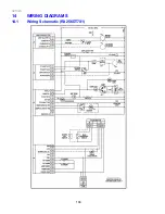
Страница 104: ...321023 104 14 WIRING DIAGRAMS 14 1 Wiring Schematic RX256DT7X1...

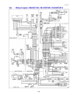
Страница 105: ...321023 105 14 2 Wiring Diagram RX256DT7X1...

Страница 106: ...321023 106 14 3 Wiring Schematic RX256DT4X1 RX256ET2B1 RX256ET2W1...

Страница 107: ...321023 107 14 4 Wiring Diagram RX256DT4X1 RX256ET2B1 RX256ET2W1...

Страница 108: ...321023 108 NOTES...

Отзывы: