321023
90
As far as pressure readings are concerned, if the restriction, such as a kinked line or a joint soldered
shut is anywhere on the low side, the suction pressure would probably be in a vacuum while the head
pressure will be near normal. If the restriction is on the high side, the suction pressure, again, will
probably be in a vacuum while the head pressure will be higher than normal during the pump out
period described earlier. In either case, it will take longer than the normal ten minutes or so for the
head pressure to equalize with the low side after the compressor stops.
12.4
Symptoms of Air in System
This can result from a low side leak or improper servicing. If a leak should occur on the low side, the
temperature control would not be satisfied; thus continuous running of the compressor would result.
The compressor would eventually pump the low side into a vacuum, drawing air and moisture into the
system. Air and R134A do not mix, so the air pressure would be added to the normal head pressure,
resulting in higher than normal head pressures.
One way to determine if air is in the system is to read the head pressure gauge with the product off
and evaporator and condenser at the same temperature and then take the temperature on the
condenser outlet tube. This temperature should be within 3° or 4° of what the Pressure-Temperature
Relation chart shows for given idle head pressure. If the temperature is considerably lower than the
idle head pressure of the gauge this would indicate there is air in the system.
Thorough leak checking is necessary. Correct the source of the leak. Do not attempt to purge off the
air because this could result in the system being undercharged. It is best to discharge, replace drier,
evacuate and recharge with the specified refrigerant charge.
12.5
Symptoms of Low or High Ambient Temperature Installation
Lower ambient air temperature reduces the condensing temperature and therefore reduces the
temperature of the liquid entering the evaporator. The increase in refrigeration effect due to operation
in a lower ambient results in a decrease in power consumption and run time. At lower ambients there
is a reduction in cabinet heat leak which is partially responsible for lower power consumption and run
time.
An increase in refrigeration effect cannot be expected below a certain minimum ambient temperature.
This temperature varies with the type and design of the product.
Generally speaking, ambient temperatures cannot be lower than 60°F without affecting operating
efficiency. Conversely, the higher the ambient temperature the higher the head pressure must be to
raise the high side refrigerant temperature above that of the condensing medium. Therefore, head
pressure will be higher as the ambient temperature rises. Refrigerators installed in ambient
temperatures lower than 60°F will not perform as well because the pressures within the system are
generally reduced and unbalanced. This means that the lower head pressure forces less liquid
refrigerant through the capillary line. The result is the symptoms of a refrigerant shortage. The lower
the ambient temperature the more pronounced this condition becomes.
When a point where the ambient temperature is below the cut-in of the Temperature Control is
reached, the compressor won't run.
The drain traps will freeze in ambient temperatures of 32°F or below.
Heat Load
A greater heat load can result from the addition of more than normal supply of foods, such as after
doing the weekly shopping. Other items contributing to an additional heat load would be excessive
door openings, poor door sealing, interior light remaining on, etc.
Содержание RX256DT4X1
Страница 11: ...321023 11 2 3 Refrigerant Flow...
Страница 12: ...321023 12 2 4 Cabinet Air Flow...
Страница 13: ...321023 13 2 5 Ice And Water Dispenser Diagram...
Страница 14: ...321023 14 2 6 Water Valve Diagram...
Страница 15: ...321023 15 2 7 Typical External Sweat Pattern...
Страница 16: ...321023 16 3 INSTALLATION...
Страница 17: ...321023 17...
Страница 18: ...321023 18...
Страница 76: ...321023 76 Ice Water Dispensing Board...
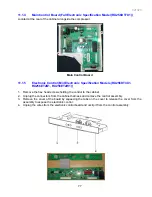
Страница 78: ...321023 78 Mid Electronic Specification Control RX256DT4X1 RX256ET2B1 RX256ET2W1...
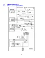
Страница 104: ...321023 104 14 WIRING DIAGRAMS 14 1 Wiring Schematic RX256DT7X1...
Страница 105: ...321023 105 14 2 Wiring Diagram RX256DT7X1...
Страница 106: ...321023 106 14 3 Wiring Schematic RX256DT4X1 RX256ET2B1 RX256ET2W1...
Страница 107: ...321023 107 14 4 Wiring Diagram RX256DT4X1 RX256ET2B1 RX256ET2W1...
Страница 108: ...321023 108 NOTES...


