26
MAINTENANCE
NOTICE!
All nuts and bolts must be installed using proper torque specifications (refer to Bolt
Torque Specifications).
1. Park prime mover on a firm, level surface with blade properly attached.
2. Place primer mover in “Park” and engage parking brake.
3. Lower the blades cutting edge onto a sturdy wood or metal blocking, positioned under the pivoting
assembly, to safely hold the wear edge 6 to 8 inches above the level surface.
4. Remove and retain all nuts and bolts but the ones at each end of the wear edge.
5. Support one end of the wear edge, remove the nut and bolt, then lower it to the level surface.
6. Support the other end, remove the nut and bolt and lower to the level surface.
7. Discard used wear edge and all nuts and bolts.
8. Support one end of the new wear edge and install with a new nut and bolt.
9. Support the other end and install a new nut and bolt
10. Install all new nuts and bolts.
11. Repeat steps 4-10 for other wear edge.
12. Install center rubber wear edge and plates with new nuts and bolts.
NOTICE!
When installing new center wear edges , 2 lock washers must be used on each bolt
for proper spacing to prevent premature wear.
NOTICE!
When installing nuts and bolts on center rubber wear edge, DO NOT tighten to
specified torque. Tighten until the retaining plate has slightly compressed the rubber.
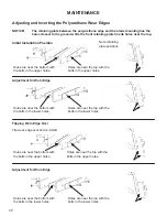
Installing New Front Wear Edges
Front Wear Edges
Center Wear Edges
Содержание V-Snow Blade
Страница 2: ...2 Notes...
Страница 17: ...17 OPERATION figure 2 figure 3 Level Scoop Position Shown...
Страница 24: ...24 MAINTENANCE RECORD Date Maintenance Procedure Performed Performed by Comments...
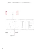
Страница 34: ...34 HYDRAULIC ELECTRIC MANIFOLD SCHEMATIC...
Страница 35: ...35 HYDRAULIC MANIFOLD SCHEMATIC...
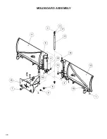
Страница 36: ...36 MOLDBOARD ASSEMBLY...
Страница 41: ...41 NOTES...


