13
Warning
Danger of electric shock
The CMMB motor controller uses mains voltage for logic supply power. Even when supply
power to the controller is switched off and the DC bus is discharged (charge lamp at front is
off), the control power input X2: L1C/L2C may still have active mains voltage.
If the LED at the front of the motor controller is on, mains voltage must be expected at X2:
L1C/L2C.
Note
Use NEBM cables (see 2.1.3) to connect the CMMB motor controller to the EMMB servo motor,
and connect the PE wire of the NEBM motor cable to the left PE screw at the front of the
motor controller.
Do not subject the NEBM cables or the wires at the X2 connector to mechanical stressing.
Comply with international and local standards and laws for the wiring and installation of live
components in the electric cabinet such as fuses, circuit breakers and contactors in relation
with the mains power supply of the motor controller.
In order to comply with EMC directive and standards, use suitable RF filters for installation of
the motor controller mains supply.
3.3.1 Selection of fuses, braking resistors and circuit breakers
Fuses, braking resistors and circuit breakers should be selected according to following specifications:
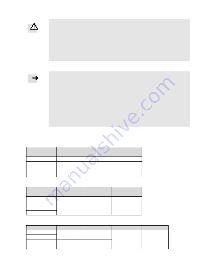
Table 3-6: Recommended fuse
Model
Control power supply fuse
(Fuse1) specification
Drive power supply fuse
(Fuse2) specification
CMMB-AS-01
1.0A/250VAC
3.5A/250VAC
CMMB-AS-02
1.0A/250VAC
3.5A/250VAC
CMMB-AS-04
1.0A/250VAC
7A/250VAC
CMMB-AS-07
1.0A/250VAC
15A/250VAC
Table 3-7: Recommended braking resistor
Model
Resistance [Ω]
Power [W]
Withstanding
voltage [VDC]
CMMB-AS-01
75
100
500
CMMB-AS-02
CMMB-AS-04
CMMB-AS-07
Table 3-8: Recommended circuit breaker
Model
Rated current[A]
Poles [P]
Voltage[VAC]
Release type
CMMB-AS-01
10
2
230
C
CMMB-AS-02
CMMB-AS-04
16
2
CMMB-AS-07


