


44
6
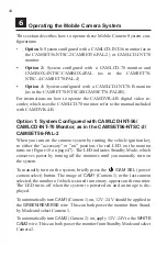
Operating the Mobile Camera System
This section describes how to operate these Mobile Camera System con-
figurations:
•
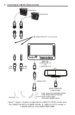
Option 1:
System configured with a CAMLCD-INT-56 monitor (as in
the CAMSET56-NTSC-2/CAMSET56-PAL-2) or CAMLCD-INT-70
monitor
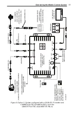
• Option 2:
System configured with a CAMLCD-70 monitor and
CAMBOX-4NTSC/CAMBOX-4PAL (as in the CAMSET70-
NTSC-4/CAMSET70-PAL-4)
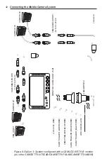
• Option 3:
System configured with a CAMLCD-INT-70-B monitor
(as in the CAMSET70-NTSC4B/CAMSET70-PAL4B)
For instructions on how to operate the CAMDVR-4-B digital video re-
corder, which uses the CAMLCD-70 monitor, refer to the manual included
with CAMDVR-4-B
Option 1: System Configured with CAMLCD-INT-56/
CAMLCD-INT-70 Monitor, as in the CAMSET56-NTSC-2/
CAMSET56-PAL-2
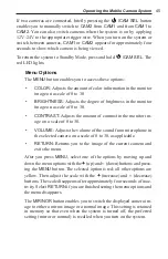
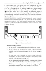
When you turn on the camera system by turning the vehicle ignition key
to either the "accessory" or "on" position, the red LED on the monitor
turns on (Figure 10 on page 47). The LED indicates Standby Mode, which
conserves power by turning off the monitors until you manually turn on
the system.
To manually turn on the system, briefly press the
/CAM SEL
(power/
camera select) button. The image of
CAM1
(Camera 1) or the last camera
selected, the number of which is stored in memory, appears on the monitor.
The LED turns off when the system is powered on and an image is dis
-
played.
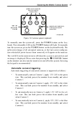
To automatically turn
CAM1
(Camera 1) on, 12V–24 V should be applied to
the
GREEN/REVERSE
wire. This can both power the monitor from Stand-
by Mode and select Camera 1.
To automatically turn
CAM2
(Camera 2) on, apply 12V–24V to the
WHITE
CAM2
wire. This can both power the monitor from Standby Mode and select
Camera 2.
Содержание CAMLCD-AHD-70
Страница 1: ...Mobile Camera Systems Installation and Operation Manual 2562397C REV C 812...
Страница 2: ...blank page...
Страница 67: ...blank page...


