Rev.23
37/311
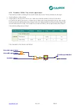
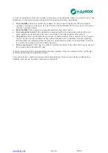
Zone 1
: The machine is deenergized for a long time. Therma image is 0%.
Zone 2
: We supply the machine with the nominal current. Thermal image evolutions so as to get the
value of the thermal balance corresponding to one time the nominal current Th = (I/It)
2
= 82%. The time
that it takes in getting the thermal balance depends on the adjusted heating constant.
Zone 3
: Once reached the thermal image corresponding to the application of one time the nominal
current, we apply 1,2 times the nominal current. Therma image will evolutione so as to get the thermal
balance corresponding to 1,2 times the nominal current Th = (I/It)
2
= 119%. This would occur if we had
the permission of the thermal function disabled. If the permission is disabled, 49 protection function
performs when the thermal image reachs the value of 100%. Once tripped, current is cutted and thermal
image is getting cool based on the cooling constant.
Zone 4
: Before getting totally cool, nominal current is applied again and thermal balnace is reached
once passed the time determined by the heating thermal constant.
Thermal image protection alarm bit is active if the thermal image measurement is over the adjusted
alarm level.
Thermal image protection trip bit is active when the measurement of the thermal image is over 100%
and it is reset when the measurement of the thermal image is under the adjusted alarm level.
4.6.2. Thermal image with memory
Thermal image is stored in non-volatile RAM memory periodically every second. By this way, though
the relay loses the power supply, it will keep the thermal status of the machine.
.
4.6.3. Thermal image measurement display. Reset.
Thermal image measuremet can be displayed on Measurement menu and Counters menu.
Display is possible in Measurement menu. Display and thermal image value reset is possible in Counters
menu.
Содержание SIL B
Страница 1: ...EN_FANOXTD_MANU_SIL_Feeder_SILB_R023 Docx USER S MANUAL SIL B Feeder Relay...
Страница 8: ...www fanox com Rev 23 8 311 2 DIMENSIONS AND CONNECTION DIAGRAMS 2 1 Equipment front view...
Страница 9: ...www fanox com Rev 23 9 311 2 2 Equipment dimensions...
Страница 10: ...www fanox com Rev 23 10 311...
Страница 11: ...www fanox com Rev 23 11 311 2 3 Cut out pattern CUT OUT PATTERN...
Страница 12: ...www fanox com Rev 23 12 311 2 4 Connection diagrams Analog connections...
Страница 13: ...www fanox com Rev 23 13 311...
Страница 14: ...www fanox com Rev 23 14 311 Digital connections Outputs and Trip circuit supervision...
Страница 15: ...www fanox com Rev 23 15 311 2 5 Terminals IEC 61850 or DNP3 0 protocols...
Страница 17: ...www fanox com Rev 23 17 311 IEC 60870 5 103 protocol...
Страница 25: ...www fanox com Rev 23 25 311 3 3 Functional diagram...
Страница 28: ...www fanox com Rev 23 28 311 3 5 1 SIL B 1 CHARGE CURVE 3 5 2 SIL B 5 CHARGE CURVE...
Страница 38: ...www fanox com Rev 23 38 311 4 6 4 Thermal protection curves This is the thermal curve for 3 minutes...
Страница 91: ...www fanox com Rev 23 91 311...
Страница 140: ...www fanox com Rev 23 140 311...
Страница 194: ...www fanox com Rev 23 194 311 Polarization V 35 0 V C Operating Angle 180 C Halfcone Angle 3 C...
Страница 307: ...www fanox com Rev 23 307 311 50BF init Fault init 79 Closure permission 52 closure permission...
Страница 308: ...www fanox com Rev 23 308 311 12 8 LED s configuration LEDs Blinking Latch Negate d LED On LED 1 LED 2 LED 3 LED 4 LED 5...
Страница 310: ...www fanox com Rev 23 310 311 NOTES...
Страница 311: ...www fanox com Rev 23 311 311...


