Rev.23
63/311
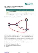
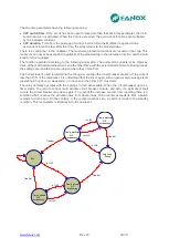
The two time parameters have the following meaning:
•
CLP switch time
: If the circuit has been open for less time than that set in this parameter, the Cold
Load Pickup is not activated. When this time is exceeded, the overcurrent functions are multiplied
by the indicated constant.
•
CLP duration
: Time from the passage of current in which time the Multiplier is applied to the
overcurrent functions tap. After this time, the relay returns to the adjusted taps
.
There is a conditioner in the multiplier. The maximum protection functions are located in their tap. This
maximum can never be exceeded, regardless of the adjusted tap in the protection function and the Cold
Load function multiplier.
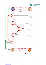
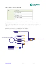
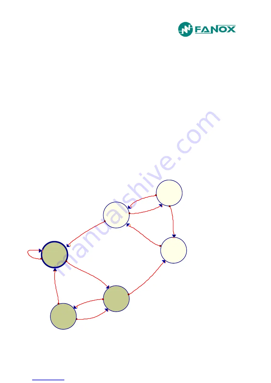
The function operated according to the following automaton. The automaton consists of six statuses,
three of them with normal adjustment, and the other three with the extended adjustments. During transit,
the settings are maintained according to where they come from.
The current level is used to determine the change, more than the circuit breaker situation. If the current
less than 10% of the rated level, it is understood that the line is open, with an extremely low usage level
(operating at night, or on weekends). In one case or the other CLP must start.
The relay normally operates with the settings in their active table. When the circuit breaker opens, a
timer starts. The remote control could activate circuit breaker closure, and also, if a permanent fault
occurs the circuit breaker may open again. To prevent the increase counter from resetting there is a
condition which reduces the activation time from where it was. If the counter exceeds its limit, a switch
is made to Cold Load. On the contrary, if the counter reaches zero, a switch is made to the standby
condition. This mechanism is identical in Cold Load reset.
Run
Time to activate
CLP
Cold Load
Pickup
Time to deactivate
CLP
Time Out
In > 10%
In < 10%
Time Out
Time to activate
CLP
Time to deactivate
CLP
Time Out
Time Out
incrementing
decrementing
incrementing
decrementing
In < 10%
In < 10%
In > 10%
In > 10%
Содержание SIL B
Страница 1: ...EN_FANOXTD_MANU_SIL_Feeder_SILB_R023 Docx USER S MANUAL SIL B Feeder Relay...
Страница 8: ...www fanox com Rev 23 8 311 2 DIMENSIONS AND CONNECTION DIAGRAMS 2 1 Equipment front view...
Страница 9: ...www fanox com Rev 23 9 311 2 2 Equipment dimensions...
Страница 10: ...www fanox com Rev 23 10 311...
Страница 11: ...www fanox com Rev 23 11 311 2 3 Cut out pattern CUT OUT PATTERN...
Страница 12: ...www fanox com Rev 23 12 311 2 4 Connection diagrams Analog connections...
Страница 13: ...www fanox com Rev 23 13 311...
Страница 14: ...www fanox com Rev 23 14 311 Digital connections Outputs and Trip circuit supervision...
Страница 15: ...www fanox com Rev 23 15 311 2 5 Terminals IEC 61850 or DNP3 0 protocols...
Страница 17: ...www fanox com Rev 23 17 311 IEC 60870 5 103 protocol...
Страница 25: ...www fanox com Rev 23 25 311 3 3 Functional diagram...
Страница 28: ...www fanox com Rev 23 28 311 3 5 1 SIL B 1 CHARGE CURVE 3 5 2 SIL B 5 CHARGE CURVE...
Страница 38: ...www fanox com Rev 23 38 311 4 6 4 Thermal protection curves This is the thermal curve for 3 minutes...
Страница 91: ...www fanox com Rev 23 91 311...
Страница 140: ...www fanox com Rev 23 140 311...
Страница 194: ...www fanox com Rev 23 194 311 Polarization V 35 0 V C Operating Angle 180 C Halfcone Angle 3 C...
Страница 307: ...www fanox com Rev 23 307 311 50BF init Fault init 79 Closure permission 52 closure permission...
Страница 308: ...www fanox com Rev 23 308 311 12 8 LED s configuration LEDs Blinking Latch Negate d LED On LED 1 LED 2 LED 3 LED 4 LED 5...
Страница 310: ...www fanox com Rev 23 310 311 NOTES...
Страница 311: ...www fanox com Rev 23 311 311...

