Rev.23
64/311
4.19. General settings
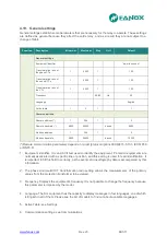
General settings establish some parameters that are necessary for the relay to operate. These settings
are defined as general because they affect the entire relay, and as a result they are not subject to a
change of table.
Function
Description
Minimum
Maximum
Step
Unit
Default
General settings
Equipment identifier
-
-
-
-
“www.fanox.com”
Transformation ratio of
the phase CTs
1
2000
1
-
100
Transformation ratio of
the neutral CTs
1
2000
1
-
100
Transformation ratio of
the VTs
1
2000
1
-
100
Frequency
-
-
60/50
Hz
50
Language
-
-
-
-
English
Active table
1
3
1
-
1
Communications
Remote address (*)
1
254
1
-
3
Remote baudrate (*)
4800
38400
-
bauds
9600
Modbus address
1
254
1
-
2
Modbus baudrate
4800
38400
-
bauds
19200
(*)Remote communication parameters depend on model (protocol options:IEC60870-5-103, IEC61850
or DNP3.0)
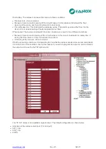
1. Equipment identifier. It is an ASCII text used to identify the equipment. Protection equipments are
normally associated with a specific line or position, and this setting is used for said identification. It
is important to fill this field in correctly, as the events and oscillography data is accompanied by this
information.
2. The phase and neutral CT transformation ratio setting allows the measurements of the primary
values from the protection transformer to be viewed.
3. Frequency. Disp
lays the equipment’s frequency.It is not possible to change the frequency because
this parameter is imposed by the model.
4. Language. The SIL equipment has the capacity to display messages in four languages, one of which
is English in all of them. Please see the list of models to find out about available languages.
5. Active Table: see Settings
6. Communication settings: see Communications
Содержание SIL B
Страница 1: ...EN_FANOXTD_MANU_SIL_Feeder_SILB_R023 Docx USER S MANUAL SIL B Feeder Relay...
Страница 8: ...www fanox com Rev 23 8 311 2 DIMENSIONS AND CONNECTION DIAGRAMS 2 1 Equipment front view...
Страница 9: ...www fanox com Rev 23 9 311 2 2 Equipment dimensions...
Страница 10: ...www fanox com Rev 23 10 311...
Страница 11: ...www fanox com Rev 23 11 311 2 3 Cut out pattern CUT OUT PATTERN...
Страница 12: ...www fanox com Rev 23 12 311 2 4 Connection diagrams Analog connections...
Страница 13: ...www fanox com Rev 23 13 311...
Страница 14: ...www fanox com Rev 23 14 311 Digital connections Outputs and Trip circuit supervision...
Страница 15: ...www fanox com Rev 23 15 311 2 5 Terminals IEC 61850 or DNP3 0 protocols...
Страница 17: ...www fanox com Rev 23 17 311 IEC 60870 5 103 protocol...
Страница 25: ...www fanox com Rev 23 25 311 3 3 Functional diagram...
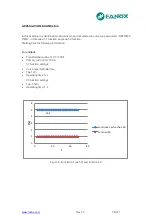
Страница 28: ...www fanox com Rev 23 28 311 3 5 1 SIL B 1 CHARGE CURVE 3 5 2 SIL B 5 CHARGE CURVE...
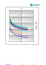
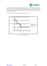
Страница 38: ...www fanox com Rev 23 38 311 4 6 4 Thermal protection curves This is the thermal curve for 3 minutes...
Страница 91: ...www fanox com Rev 23 91 311...
Страница 140: ...www fanox com Rev 23 140 311...
Страница 194: ...www fanox com Rev 23 194 311 Polarization V 35 0 V C Operating Angle 180 C Halfcone Angle 3 C...
Страница 307: ...www fanox com Rev 23 307 311 50BF init Fault init 79 Closure permission 52 closure permission...
Страница 308: ...www fanox com Rev 23 308 311 12 8 LED s configuration LEDs Blinking Latch Negate d LED On LED 1 LED 2 LED 3 LED 4 LED 5...
Страница 310: ...www fanox com Rev 23 310 311 NOTES...
Страница 311: ...www fanox com Rev 23 311 311...

