


Rev.23
137/311
7.2.
Remote communications ports.
SILB with two ports RS485 one for ModBus and the other one for IEC60870-5-
103
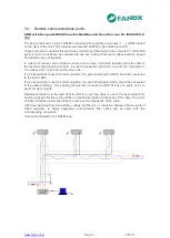
The device features 2 exterior RS485 connections through three terminals (+, - y GND) located
on the back of the unit. The protocols used are IEC 60870-5-103 and Modbus RTU
These ports can be used for the continuous monitoring of the device from a remote PC or SCADA
system. Up to 32 units can be connected to one bus, each with its own modbus address. Speed
and direction are configurable.
In order to minimize communications errors due to noise, a shielded twisted conductor cable is
the recommended physical medium. In order to make the connection, connect all + terminals on
one side and all
– terminals on the other side.
If a 3 strand cable is used for communication, the ground terminals (GND) should be connected
to the earth cable.
If a 2 strand cable is used for communication, the ground terminals (GND) should be connected
to the cable shielding. The shielding should be connected to GND at only one point, so as to
avoid circular currents.
Resistance loads must be used at both ends if a very long cable is used. The best solution for
avoiding signal reflection is the addition of resistance loads at both ends of the cable. The value
of these resistance loads should be the same as the impedance of the cable.
rs485 are insulated from the auxiliary voltage, but there is no insulation between the two ends of
rs485 terminals. In highly aggressive environments fiber optics can be used, with the
corresponding converters.
Connection diagram of an RS485 bus:
Содержание SIL B
Страница 1: ...EN_FANOXTD_MANU_SIL_Feeder_SILB_R023 Docx USER S MANUAL SIL B Feeder Relay...
Страница 8: ...www fanox com Rev 23 8 311 2 DIMENSIONS AND CONNECTION DIAGRAMS 2 1 Equipment front view...
Страница 9: ...www fanox com Rev 23 9 311 2 2 Equipment dimensions...
Страница 10: ...www fanox com Rev 23 10 311...
Страница 11: ...www fanox com Rev 23 11 311 2 3 Cut out pattern CUT OUT PATTERN...
Страница 12: ...www fanox com Rev 23 12 311 2 4 Connection diagrams Analog connections...
Страница 13: ...www fanox com Rev 23 13 311...
Страница 14: ...www fanox com Rev 23 14 311 Digital connections Outputs and Trip circuit supervision...
Страница 15: ...www fanox com Rev 23 15 311 2 5 Terminals IEC 61850 or DNP3 0 protocols...
Страница 17: ...www fanox com Rev 23 17 311 IEC 60870 5 103 protocol...
Страница 25: ...www fanox com Rev 23 25 311 3 3 Functional diagram...
Страница 28: ...www fanox com Rev 23 28 311 3 5 1 SIL B 1 CHARGE CURVE 3 5 2 SIL B 5 CHARGE CURVE...
Страница 38: ...www fanox com Rev 23 38 311 4 6 4 Thermal protection curves This is the thermal curve for 3 minutes...
Страница 91: ...www fanox com Rev 23 91 311...
Страница 140: ...www fanox com Rev 23 140 311...
Страница 194: ...www fanox com Rev 23 194 311 Polarization V 35 0 V C Operating Angle 180 C Halfcone Angle 3 C...
Страница 307: ...www fanox com Rev 23 307 311 50BF init Fault init 79 Closure permission 52 closure permission...
Страница 308: ...www fanox com Rev 23 308 311 12 8 LED s configuration LEDs Blinking Latch Negate d LED On LED 1 LED 2 LED 3 LED 4 LED 5...
Страница 310: ...www fanox com Rev 23 310 311 NOTES...
Страница 311: ...www fanox com Rev 23 311 311...


