


Updating Firmware
Firmware for the TLP 350CV can be upgraded using the extron Firmware Loader, a web
browser and the default web pages, or GUI Configurator. before starting, consult your IT
team and ensure that the TLP 350CV has a unique IP address.
before an upgrade, visit
www.extron.com
to obtain the latest firmware.
NOTE:
The factory default IP address for the TLP 350CV is 192.168.254.254. Consult
with your IT Department to ensure all IP addresses are correctly assigned.
Obtaining the Firmware Update File
Firmware update files are located on the software disc that ships with unit or can be
downloaded, free of charge, from the extron website (
www.extron.com
).
To download a firmware file to a computer:
1.
Power on a computer with internet access.
2.
To download firmware for the TouchLink panel unit:
a.
From the Software Products disc, insert the disc into the DVD ROM drive and select
the
Firmware
tab. Locate the firmware file and click
Install
. Follow the on-screen
instructions to download the file. Note the file location.
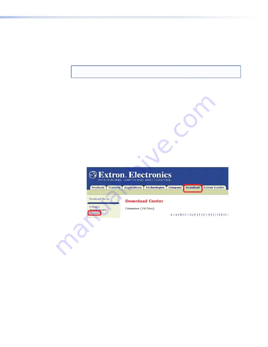
b.
From the extron web site (
www.extron.com
), select the
Download
tab, then click
on the
Firmware
selection. Locate the firmware file and click
Download
. Follow
the on-screen instructions to download the file. Note the file location.
Figure 28.
Extron Web Page — Download Center
3.
Use the update method of your choice to install the new firmware.
41
TLP 350CV • Reset Modes and Button Replacement
Содержание TouchLink TLP 350CV
Страница 4: ......
Страница 6: ...TLP 350CV Contents vi ...
Страница 27: ...Figure 10 Touchpanel Configuration TLP 350CV Configuration Software 21 ...