background image

21

INSTALLATION

Caution: Before assembling, installing, or connecting any components, 

follow the safety information in the ETS-Lindgren 

Product Information 

Bulletin

 included with your shipment.

Proper installation of the MAPS directly affects performance. 

The installation must be performed by factory installation 

specialists or individuals authorized by ETS-Lindgren to 

perform installation. This information provided in this manual 

is intended to be used only by those installation specialists.
See the assembly drawings located in the back pocket of the 

manual to assist with installation.

Note: 

The  MAPS mast assembly is incompatible with the prior versions of the 

mast assembly due to a change in the gear ratio to facilitate the higher speed 
of the mast. To upgrade a mast, contact ETS-Lindgren.

The installation of the Multi Axis Positioning System (MAPS™) will take approximately eight hours and will require 
a minimum of two people.
If you have any questions concerning installation, contact ETS-Lindgren Customer Service.

Required Tools

The following tools are required to install the MAPS:
•  Power hand drill, 3/8 in chuck
•  Drill bit, 3/16 in diameter
•  Drive bit, square (provided)
•  Drive bit, #2 Phillips
•  SAE hex key wrench set (maximum 1/2 in)
•  Permanent marker
•  Laser level, 5 beam, and stand
•  Bubble level (36 in minimum)
•  10 in adjustable, open ended wrench

Содержание ETS-LINDGREN MAPS 2112 Series

Страница 1: ...Multi Axis Positioning System MAPSTM User Manual 1719784 Rev A May 2020...

Страница 2: ......

Страница 3: ...it described herein nor does it convey any license under its patent rights nor the rights of others All trademarks are the property of their respective owners Copyright 2020 by ETS Lindgren Inc All Ri...

Страница 4: ...4...

Страница 5: ...MAINTENANCE 13 Belt Tension 13 Routine Maintenance 13 Bi Annual Maintenance 13 Annual Maintenance 13 Replacement Parts 14 Optional Parts 2117 NNNN Only 15 Service Procedures 16 Contacting ETS Lindgren...

Страница 6: ...Using the Tension Scale to Measure and Set Belt Tension 26 Upper Drive Unit Removal 28 Bore Sight and Leveling 29 Bore Sight 29 Leveling and Height Adjustment 32 Controller Interface 33 Absorber Insta...

Страница 7: ...product is marked with this symbol see the instruction manual for additional information If the instruction manual has been misplaced download it from ets lindgren com or contact ETS Lindgren Custome...

Страница 8: ...8...

Страница 9: ...al support column controls the movement of the MAPS in conjunction with a positioning controller sold separately such as the EMCenter Modular RF Platform To minimize potential radio frequency RF obstr...

Страница 10: ...he MAPS includes a 63 in 160 cm diameter circular wood deck that is bolted onto a motorized turntable The deck has an opening for the vertical support and access to the knobs that clamp the sliding ca...

Страница 11: ...also expandable with a variety of additional options available Please contact ETS Lindgren with any questions Note Existing ETS Lindgren positioning controllers can be used with the Model 2112 2117 2...

Страница 12: ...ormation Bulletin included with your shipment for the following Warranty information Safety regulatory and other product marking information Steps to receive your shipment Steps to return a component...

Страница 13: ...APS and surrounding absorber Attempt to rotate each axis by hand Excessive rotation may indicate a loose drive component Check the belt tension and make any necessary adjustments During operation list...

Страница 14: ...9 5 inches is 5950 Replacement Part Description 2112 NNNN Part Number 2117 NNNN Part Number 2122 NNNN Part Number MAPS Turntable Assembly 111040 Mast Assembly 114839 NNNN 114492 NNNN 117745 NNNN Mount...

Страница 15: ...o mount laptop or similar device EUT rotation axis is at center of EUT 108279 Optional Part Description Part Number Mounting Adapters for Model 3160 Standard Gain Horn Antennas Requires antenna mount...

Страница 16: ...formation Sending a Component for Service For the steps to return a system or system component to ETS Lindgren for service see the Product Information Bulletin included with your shipment Calibration...

Страница 17: ...eter 160 02 cm 63 in Typical Turntable Platform Height 36 96 cm 14 55 in Approximate Installed Unit Weight 453 59 kg 1000 lb Mast Specifications 2112 2117 2122 Height Customer specified Maximum EUT Lo...

Страница 18: ...18...

Страница 19: ...be protected from excess current according to local electrical codes Integral circuit protection is provided in the motor base assembly 2 Make sure the conductor size is adequate for the motor load an...

Страница 20: ...20...

Страница 21: ...with installation Note The MAPS mast assembly is incompatible with the prior versions of the mast assembly due to a change in the gear ratio to facilitate the higher speed of the mast To upgrade a ma...

Страница 22: ...chor plates for the turntable and should only be used as a guide in centering the turntable portion of the MAPS 1 Locate the reference point It is generally located along the bore axis of the range an...

Страница 23: ...do not drill anchor holes through the floor joint strips Use the shim plates provided 1 Remove the wood deck 2 The drive units are designed to move from the shipping container to the chamber floor as...

Страница 24: ...4 Use a bubble level to verify the turntable unit is flat This is a preliminary check only final leveling of the turntable will be completed in a later step 5 Use shim plates to level the table The s...

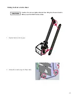
Страница 25: ...liding the Belt onto the Mast Caution Do not over tighten the belt See Using the Tension Scale to Measure and Set Belt Tension below 1 Slip belt onto motor box gear 2 Clamp down mast using the three k...

Страница 26: ...belt does not require a high degree of tension for normal operation Caution Using the included tension scale follow the steps in this section to set the belt tension for the MAPS 48 oz maximum Located...

Страница 27: ...ensioner 3 Pull the belt tensioner to the right with the scale until the scale reads 48 oz This is the maximum belt tension recommended 4 Holding the scale steady at 48 oz re tighten the belt tensione...

Страница 28: ...the bracket on the opposite side of the unit that ties the drive unit to the turntable top This temporary bracket holds the unit in place for shipping 6 Turn the brake knob to release the drive unit...

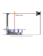
Страница 29: ...laser level Following are the typical installation steps used to achieve bore sight 1 Locate and mark the center of the chamber wall opposite the range antenna mounted in the chamber end wall Marking...

Страница 30: ...horizontal laser in line with the antenna mounted in the end wall of the chamber Align the opposite side of the horizontal laser through the mounting gear to the center of the opposite end wall and t...

Страница 31: ...31 Align laser through the mast mount to the center of the chamber 5 Beam Laser...

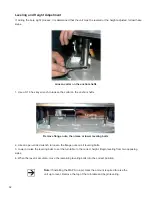
Страница 32: ...turntable and begin leveling 1 Use a 3 16 hex key wrench to loosen the collar on the anchor shafts 2 Use an open ended wrench to loosen the flange nuts on all leveling bolts 3 Lower or raise the level...

Страница 33: ...it switch 10 Position the actuating pins in the holes on each side of the access port Controller Interface For information about connecting fiber optic cables from the MAPS to the positioning controll...

Страница 34: ...34...

Страница 35: ...ontroller manual for information on connecting the fiber optic cable Use the controller to check the clockwise CW and counterclockwise CCW rotation in both directions by a few degrees The position in...

Страница 36: ...36...

Страница 37: ...MAPS Duration of Warranties All product warranties except the warranty of title and all remedies for warranty failures are limited to two years Product Warranted Duration of Warranty Period 2112 Mult...

Страница 38: ......

Отзывы: