SM-900.4407
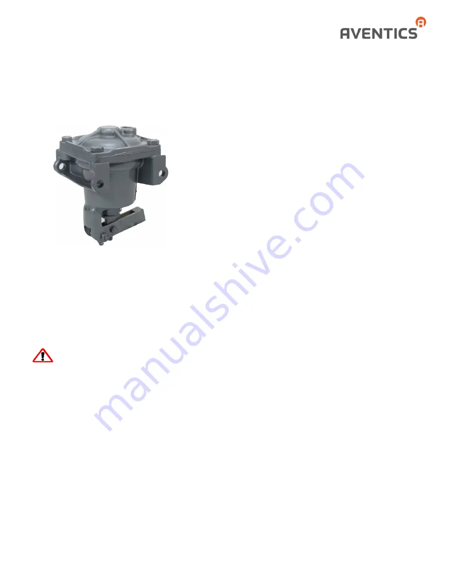
A-2-H Actuator Positioners
Service Information
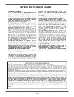
The user of these devices must conform to all applicable
electrical, mechanical, piping and other codes in the
installation, operation or repair of these devices.
INSTALLATION!
Do not attempt to install, operate or repair
these devices without proper training in the technique of
working on pneumatic or hydraulic systems and devices,
unless under trained supervision.
Compressed air and hydraulic systems contain high levels of
stored energy. Do not attempt to connect, disconnect or
repair these products when a system is under pressure.
Always exhaust or drain the pressure from a system before
performing any service work. Failure to do so can result in
serious personal injury.
MOUNTING!
Devices should be mounted and positioned in
such a manner that they cannot be accidentally operated.
WARNING: INSTALLATION AND
MOUNTING
The A-2-H Actuator Positioner is a pneumatic positioner
used where accuracy is required and when the device to be
operated has low-force characteristics. Typical applications
are positioning the butterfly valve of carburetors and the
control arm of diesel engine governors.
INSTALLATION and ADJUSTMENT
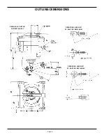
Mount the positioner firmly to the engine frame to
prevent relative motion between the operating lever
and the engine control arm. The positioner should be
installed with its operating lever in the same plane as
the engine control arm. Avoid interference with the
connecting link which could cause friction and
inaccuracy. Adjustable clevis and ball joint lever
attachments are available.
Full travel range of the positioner should be utilized
and the end travel of the lever attachment and the
engine control arm must match. The lever with
attachment is adjustable in length from 3 ¾ inches to
4 ½ inches (95mm to 114mm), which alters the end
travel from 1 7/8 inches to 2 ¼ inches (48mm to
57mm). For decreased lever travel, loosen jam nut
(100) and screw the attachment farther into the
operating lever. Tighten the jam nut to secure this
position. Lever travel can be increased by
unscrewing the attachment and then tightening the
jam nut.
If the end travel of the engine control arm exceeds
the maximum adjustment of the operating lever, the
normal procedure is to drill a hole in the control arm
at a point which has a travel range of two inches.
Fasten the connecting link to the new hole and
readjust the end travel of the control arm and
operating lever to match.
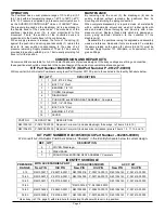
As assembled, the adjustable elements of the
positioner are matched to provide zero lever travel
with indicated preload pressure (usually 10 psi or 0.7
bar), and maximum lever travel with rated top
pressure (usually 60 psi or 4.1 bar).
The push rod travel is factory-set to correspond to
rated top pressure. If the top pressure of the control
valve is greater or less than that of the positioner, the
travel of the control valve handle can be made to
match the travel of the operating lever by using the
push rod travel adjusting screw (15).
Two or more positioners can be matched to
provide the same movement for a given change in air
pressure. They can also be deliberately mismatched
to provide different lever travel to compensate for
inequalities in operating characteristics of the
controlled device. If necessary to adjust for incorrect
initial pressure, remove or add shims (9 and 10) as


