background image

Installation  4. First Step 
 

10 

T-B series  Rev.1


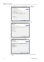
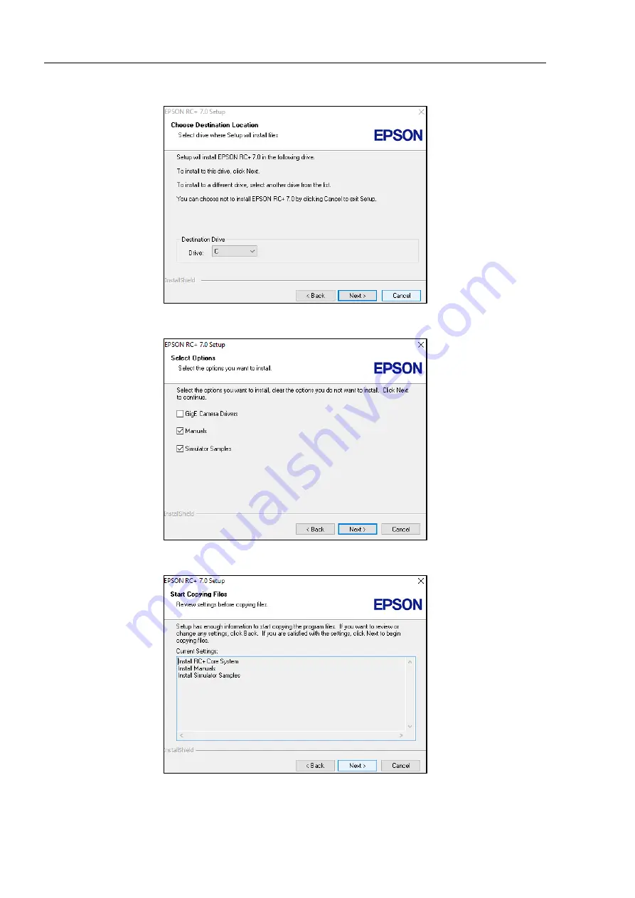
(4)  Select the drive where you want to install EPSON RC+ 7.0 and click <Next>. 

The installation directory is called EpsonRC70. This cannot be changed. 


(5)  The dialog for selecting the options to be installed will be displayed.   

Check the options you want to install and click <Next>. 


(6)  The dialog to review the settings will be displayed.   

If you are satisfied with the settings, click <Next>. 


(7)  If required, install “Windows Installer” on your system. This may take several 

minutes. 


Содержание T-B Series

Страница 1: ...SCARA ROBOT T B series MANUAL Rev 1 EM217R4788F ...

Страница 2: ...SCARA Robots T B series Manual Rev 1 ...

Страница 3: ...T B series Rev 1 i SCARA ROBOT T B series Manual Rev 1 Copyright 2021 SEIKO EPSON CORPORATION All rights reserved ...

Страница 4: ...system safety and correctly TRADEMARKS Microsoft Windows and Windows logo are either registered trademarks or trademarks of Microsoft Corporation in the United States and or other countries Other brand and product names are trademarks or registered trademarks of the respective holders TRADEMARK NOTATION IN THIS MANUAL Microsoft Windows 8 Operating system Microsoft Windows 10 Operating system Throu...

Страница 5: ...bols Pb Cd or Hg indicates if these metals are used in the battery This information only applies to customers in the European Union according to DIRECTIVE 2006 66 EC OF THE EUROPEAN PARLIAMENT AND OF THE COUNCIL OF 6 September 2006 on batteries and accumulators and waste batteries and accumulators and repealing Directive 91 157 EEC and legislation transposing and implementing it into the various n...

Страница 6: ...pport for the network connection The network connecting function Ethernet on our products assumes the use in the local network such as the factory LAN network Do not connect to the external network such as Internet In addition please take security measure such as for the virus from the network connection by installing the antivirus software Security support for the USB memory Make sure the USB mem...

Страница 7: ... 0 and the robot system are available Compatible Connection is OK It is recommended to use the EPSON RC 7 0 Ver 7 5 1A or later Display or control may not be operated properly Shape of Motors The shape of the motors used for the Manipulator that you are using may be different from the shape of the motors described in this manual because of the specifications Setting by Using Software This manual c...

Страница 8: ...ctions specifications etc required for the Manipulator installation and design Daily inspection of the Manipulator Status Code Error Code List PDF This manual contains a list of code numbers displayed on the controller and messages displayed in the software message area The manual is primarily intended for people who design robot systems or do programming T B series Maintenance Manual PDF Controll...

Страница 9: ...ving the Factory Default 8 4 First Step 9 4 1 Installing EPSON RC 7 0 Software 9 4 2 Development PC and Manipulator Connection 11 4 2 1 About Development PC Connection Port 12 4 2 2 Precautions 12 4 2 3 Software Setup and Connection Check 12 4 2 4 Backup the Initial Condition of the Manipulator 13 4 2 5 Disconnection of Development PC and Manipulator 13 4 2 6 Moving the Manipulator to Initial Posi...

Страница 10: ...Specifications 39 2 1 Model Number 39 2 2 Part Names 40 2 2 1 T3 B 40 2 2 2 T6 B 41 2 3 Outer Dimensions 42 2 3 1 T3 B 42 2 3 2 T6 B 43 2 4 System Example 44 2 5 Specifications 45 2 6 How to Set the Model 45 3 Environments and Installation 46 3 1 Environmental Conditions 46 3 2 Base Table 48 3 3 Mounting Dimensions 49 3 4 Unpacking and Transportation 51 3 5 Installation Procedure 52 3 6 Power Supp...

Страница 11: ...etting the Mechanical Stop of Joint 3 82 5 3 Setting the Cartesian Rectangular Range in the XY Coordinate System of the Manipulator for Joints 1 and 2 84 5 4 Standard Motion Range 84 6 Operation Mode LED 85 6 1 Overview 85 6 2 Switch Operation Mode 85 6 3 Program Mode AUTO 86 6 3 1 What is Program Mode AUTO 86 6 3 2 Setup from EPSON RC 7 0 86 6 4 Auto Mode AUTO 87 6 4 1 What is Auto mode AUTO 87 6...

Страница 12: ...h 104 11 1 2 Latch Release Switch 104 11 1 3 Checking Latch Release Switch Operation 105 11 2 Emergency Stop Switch Connection 105 11 2 1 Emergency Stop Switch 105 11 2 2 Checking Emergency Stop Switch Operation 106 11 2 3 Recovery from Emergency Stop 106 11 3 Pin Assignments 107 11 4 Circuit Diagrams 108 11 4 1 Example 1 External emergency stop switch typical application 108 11 4 2 Example 2 Exte...

Страница 13: ...t Signals 124 14 1 2 Remote Output Signals 128 14 2 Timing Specifications 132 14 2 1 Precautions for Remote Input Signals 132 14 2 2 Timing Diagram for Operation Execution Sequence 132 14 2 3 Timing Diagram for Program Execution Sequence 132 14 2 4 Timing Diagram for Safety Door Input Sequence 133 14 2 5 Timing Diagram for Emergency Stop Sequence 133 15 SD Card Slots 134 16 Fieldbus I O 135 17 Res...

Страница 14: ...et Head Cap Bolts 150 Appendix Appendix A Specifications 153 T3 B Specifications 153 T6 B Specifications 156 Appendix B Time and Distance of Free Running in Emergency 159 T3 B Time and Distance of Free Running in Emergency 160 T3 B401S J1 160 T3 B401S J2 160 T3 B401S J3 160 T6 B Time and Distance of Free Running in Emergency 161 T6 B602S J1 161 T6 B602S J2 161 T6 B602S J3 161 Appendix C Time and D...

Страница 15: ...TABLE OF CONTENTS T B series Rev 1 xiii T6 B602S J3 165 Appendix D Open Source Software License 167 ...

Страница 16: ...TABLE OF CONTENTS xiv T B series Rev 1 ...

Страница 17: ...Installation This volume describes the flow from unpacking to operation and designing the robot system ...

Страница 18: ......

Страница 19: ...you find anything unclear 1 1 Conventions Important safety considerations are indicated throughout the manual by the following symbols Be sure to read the descriptions shown with each symbol WARNING This symbol indicates that a danger of possible serious injury or death exists if the associated instructions are not followed properly WARNING This symbol indicates that a danger of possible harm to p...

Страница 20: ...I O USB for save USB for development ModBus Fieldbus Slave Option Illustration T3 B401S 1 EPSON RC 7 0 supports the following OS Windows 8 1 Pro EPSON RC 7 0 Ver 7 1 0 or later Windows 10 Pro EPSON RC 7 0 Ver 7 2 0 or later 2 Either teaching pendant is available 3 If connecting to T3 B T6 B Manipulator dedicated convert cable is necessary ...

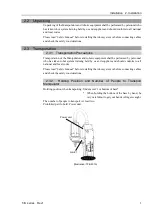
Страница 21: ...Manipulators and robotic equipment shall be performed by personnel who has taken robot system training held by us and suppliers and should conform to all national and local codes Please read Safety Manual before installing the robot system or before connecting cables and check the safety considerations 2 3 2 Holding Position and Number of People to Transport Manipulator Holding position when trans...

Страница 22: ...des Please read Safety Manual before installing the robot system or before connecting cables and check the safety considerations For details refer to T3 B T6 B Manipulator 3 Environments and Installation 2 5 Connection to EMERGENCY Connector Connect a safeguard switch or Emergency Stop switch to the EMERGENCY connector for safety When nothing is connected to the EMERGENCY connector Controller does...

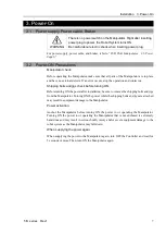
Страница 23: ... Shipping bolts and jigs check before turning ON Before turning ON the power after installation be sure to remove the shipping bolts and jigs from the Manipulator Turning ON the power while the shipping bolts and jigs are attached may result in equipment damage to the Manipulator Power activation Anchor the Manipulator before turning ON the power to or operating the Manipulator Turning ON the powe...

Страница 24: ...p normally If the ERROR LED is turned ON or blinking check connection in step 1 to 4 and turn ON the power again If the ERROR LED is still ON or blinking contact the supplier in your region LED Illustration T3 B401S 3 4 Saving the Factory Default The manipulator you purchased is set up in the manipulator as the factory default It is recommended to save the factory default state of the Controller i...

Страница 25: ...ure that the Robot system is installed safely by following the description in 1 Safety and 2 Installation Then operate the Robot system in the following procedures 4 1 Installing EPSON RC 7 0 Software The EPSON RC 7 0 software needs to be installed on your development PC 1 Insert the EPSON RC 7 0 Setup DVD in the DVD drive 2 The following dialog will be displayed Click Next 3 Enter your user name ...

Страница 26: ...lled EpsonRC70 This cannot be changed 5 The dialog for selecting the options to be installed will be displayed Check the options you want to install and click Next 6 The dialog to review the settings will be displayed If you are satisfied with the settings click Next 7 If required install Windows Installer on your system This may take several minutes ...

Страница 27: ...tallation is now completed When installing RC an error Cannot create parser instance may occur If the error occurs uninstall RC once and execute Microsoft VC151719 exe in the DVD and re install RC 4 2 Development PC and Manipulator Connection Connect the development PC and the development PC connection port for connection Illustration T3 B401S For other details of development PC and Manipulator co...

Страница 28: ...4 2 2 Precautions When connecting the development PC and the Manipulator make sure of the following Connect the development PC and the Manipulator with 5 m or shorter USB cable Do not use the USB hub or extension cable Make sure that no other devices except development PC is used for development PC connection port Use PC or USB cable that supports USB2 0 HighSpeed mode to operate in USB2 0 HighSpe...

Страница 29: ...on Drive to an arbitrary drive 3 Click OK The project will be copied to the external media 4 From the Tools menu select Controller 5 Click on the Backup Controller button 6 Select the arbitrary drive 7 Click OK The system configuration will be backed up on the external media 4 2 5 Disconnection of Development PC and Manipulator Disconnection of the development PC and the Manipulator is indicated 1...

Страница 30: ...usly Releasing the brakes of two or more joints simultaneously may result in hands or fingers being caught and or equipment damage to or malfunction of the Manipulator as the arms of the Manipulator may move in unexpected directions Be careful of the arm falling when releasing the brake While the brake is being released the Manipulator s arm falls by its own weight The arm falling may result in ha...

Страница 31: ... Command Window Motor On Go Pulse 0 0 0 0 For position and posture of Manipulator at 0 pulse position refer to T3 B T6 B Manipulator 5 Motion Range in the Manipulator manuals C Jog motion from the EPSON RC Move the Manipulator by exciting the motors and operating from the Jog Teach window of the EPSON RC 1 Start the EPSON RC 7 0 Double click the EPSON RC 7 0 icon on the desktop 2 Create a new proj...

Страница 32: ... Control Panel tab is open Click the MOTOR ON button 5 Move the Manipulator with Jog motion 1 Select Jog Teach tab 2 Select Joint in Jogging Mode 3 Move the Manipulator by joint by clicking J1 J4 jog keys Manipulator can be moved by setting to other modes or setting the jog distance ...

Страница 33: ...1 Start EPSON RC 7 0 Double click the EPSON RC 7 0 icon on the desktop 2 Create a new project 1 Select New from the Project Menu The New Project dialog box will be displayed 2 Type a project name in the New Project Name box e g FirstApp 3 Click the OK button to create the new project When the new project is created a program called Main prg is created The window titled Main prg will be displayed w...

Страница 34: ...Installation 4 First Step 18 T B series Rev 1 3 Edit the program Type the following program lines in the Main prg edit window Function main Print This is my first program Fend ...

Страница 35: ...ring project build your program is compiled and linked Then communications is established with the Manipulator and project files are sent to the Controller If there are no errors during build the Run window will appear 3 Click the Start button on the Run window to run the program 4 The tasks like the following will be displayed in the status window 19 32 45 Task main started 19 32 45 All tasks sto...

Страница 36: ...5 Teach robot points 1 Make sure that it is safe to operate the Manipulator Click the Robot Manager button on the toolbar to display the Robot Manager window 2 Click the Control Panel tab Then click the Motor On button to turn on the Manipulator motors You will be prompted to confirm the operation 3 Click the Yes button to continue ...

Страница 37: ...o lower the Z axis of the Manipulator 8 Select P1 in the Point P dropdown list which is next to the Teach button The current point is set to P1 9 Click the Teach button You will see a confirmation message to teach the point 10 Click the Yes button 11 Click the X button to jog the Manipulator in the X direction 12 Select P2 in the Point P dropdown list which is next to the Teach button The current ...

Страница 38: ...will move to each of the points you taught at 20 speed acceleration and deceleration The Power High statement executes the program to operate the robot with increased speed and acceleration and deceleration 8 Backup the project and system configuration Even though this is only a sample project we will backup the project and Manipulator configuration Backup can be done easily with EPSON RC 7 0 It i...

Страница 39: ... 1 2 Ethernet EPSON RC 7 0 User s Guide 1 9 Security for Controller Ethernet Connection 1 10 Security for Compact Vision CV2 A Ethernet Connection 1 11 Security for Feeder Ethernet Connection 4 3 3 Ethernet Communication T3 B T6 B Manipulator 9 LAN Ethernet Port 5 2 Ethernet Connection of Development PC and Manipulator EPSON RC 7 0 User s Guide 1 9 Security for Controller Ethernet Connection 1 10 ...

Страница 40: ...Installation 5 Second Step 24 T B series Rev 1 ...

Страница 41: ...T3 B T6 B Manipulator This volume contains information for setup and operation of the Manipulators Please read this volume thoroughly before setting up and operating the Manipulators ...

Страница 42: ......

Страница 43: ... anything unclear 1 1 Conventions Important safety considerations are indicated throughout the manual by the following symbols Be sure to read the descriptions shown with each symbol WARNING This symbol indicates that a danger of possible serious injury or death exists if the associated instructions are not followed properly WARNING This symbol indicates that a danger of possible serious injury ca...

Страница 44: ...ust be used within the environmental conditions described in their respective manuals This product has been designed and manufactured strictly for use in a normal indoor environment Using the product in an environment that exceeds the specified environmental conditions may not only shorten the life cycle of the product but may also cause serious safety problems The robot system must be used within...

Страница 45: ...lt in serious bodily injury and or severe equipment damage to the robot system Do not enter the operating area of the Manipulator while the power to the robot system is turned ON Entering the operating area with the power ON is extremely hazardous and may cause serious safety problems as the Manipulator may move even if it seems to be stopped Before operating the robot system make sure that no one...

Страница 46: ...arings are likely to cause oil film shortage in such situation To prevent early breakdown move each joint larger than 50 degrees for about once an hour Joint 3 If the up and down motion of the hand is less than 10 mm move the joint a half of the maximum stroke for about once an hour Oscillation resonance may occur continuously in low speed Manipulator motion Speed approx 5 to 20 depending on combi...

Страница 47: ...ulator is operating If you attempt to stop the Manipulator in emergency situations make sure to stop the Manipulator using the E STOP of the Controller If the Manipulator is stopped by turning OFF the power while it is operating following problems may occur Reduction of the life and damage of the reduction gear unit Position gap at the joints In addition if the manipulator was forced to be turned ...

Страница 48: ...cy The Manipulator in operation cannot stop immediately after the Emergency Stop switch is pressed In addition time and distance of the free running vary by following factors Hand weight WEIGHT Setting ACCEL Setting Workpiece weight SPEED Setting Posture etc For time and distance of the Manipulator free running refer to Appendix B Time and Distance of Free Running in Emergency ...

Страница 49: ...details of wiring instructions refer to 11 EMERGENCY WARNING The EMERGENCY connector on the Manipulator has a safeguard input circuit to connect the safety device interlock switch To protect operators working near the robot be sure to connect the interlock switch and make sure that it works properly The time to stop the robot and the stopping distance by the safeguard interlock function will chang...

Страница 50: ...oint 2 rotating Joint 3 up and down Joint 4 rotating Arm 1 Arm 2 Shaft Illustration T3 B401S The brake release switch affects only Joint 3 When the brake release switch is pressed in emergency mode the brake for Joint 3 is released Be careful of the shaft while the brake release switch is pressed because the shaft may be lowered by the weight of an end effector When the following errors are occurr...

Страница 51: ...ollows depending on the Z axis height ACCELS setting values by Z axis height and tip load T3 B Z axis height mm Tip load 1kg or less 2kg or less 3kg or less __ 0 Z _ 50 10000 or less _ 50 Z 100 100 Z 150 T6 B Z axis height mm Tip load 1kg or less 2kg or less 3kg or less __ 0 Z _ 50 10000 or less _ 50 Z 100 100 Z 150 150 Z 200 Z Z axis height 0 Origin position If the Manipulator is operated in CP m...

Страница 52: ...is moving The robot arm may collide against the operator This is extremely hazardous and may result in serious safety problems C Hazardous voltage exists while the Manipulator is ON To avoid electric shock do not touch any internal electric parts D You can catch your hand or fingers between the shaft and cover when bringing your hand close to moving parts H Do not connect the followings to the TP ...

Страница 53: ...T3 B T6 B Manipulator 1 Safety T B series Rev 1 37 Location of Labels T3 B C 1 C B D 1 C C C 2 A D 2 C 1 H Location of Labels T6 B 1 B C D C C A C 2 C 1 H ...

Страница 54: ...l device etc discontinue use and contact the supplier 1 9 2 Getting body caught in Manipulator When the operator is caught between the Manipulator and a mechanical part such as a base table press the emergency stop switch to release the brake on the subject arm and then move the arm by hand How to release a brake For details refer to 1 6 Emergency Movement Without Drive Power ...

Страница 55: ...ries Rev 1 39 2 Specifications 2 1 Model Number T3 B 40 1 S Environment S Standard Arm length 40 400 mm 60 600 mm Payload 3 3 kg 6 6 kg For details on the specifications refer to Appendix A T3 B T6 B Specifications Joint 3 stroke 1 150 mm 2 200 mm ...

Страница 56: ...ctor LAN Ethernet Connector Port of PC for development RESET Switch Fittings white for ø6 mm pneumatic tube Power Unit MEMORY Port Hand I O Connecter The brake release switch affects only Joint 3 When the brake release switch is pressed in emergency mode the brake for Joint 3 is released While the LED lamp is on the current is being applied to the manipulator Performing any work with the power ON ...

Страница 57: ...ctor LAN Ethernet Connector Port of PC for development RESET Switch Fittings white for ø6 mm pneumatic tube Power Unit MEMORY Port Hand I O Connecter The brake release switch affects only Joint 3 When the brake release switch is pressed in emergency mode the brake for Joint 3 is released While the LED lamp is ON current is applied to the manipulator Performing any work with the power ON is extreme...

Страница 58: ...T3 B T6 B Manipulator 2 Specifications 42 T B series Rev 1 2 3 Outer Dimensions 2 3 1 T3 B ...

Страница 59: ...T3 B T6 B Manipulator 2 Specifications T B series Rev 1 43 2 3 2 T6 B ...

Страница 60: ...nd I O USB for save USB for development ModBus Fieldbus Slave Option Illustration T3 B401S 1 EPSON RC 7 0 supports the following OS Windows 8 1 Pro EPSON RC 7 0 Ver 7 1 0 or later Windows 10 Pro EPSON RC 7 0 Ver 7 2 0 or later 2 Either teaching pendant is available 3 When connecting to T3 B T6 B specified convert cable is necessary ...

Страница 61: ...l be sure to set the Manipulator model properly Improper setting of the Manipulator model may result in abnormal or no operation of the Manipulator and or cause safety problems If the custom specifications number MT is described on MODEL of the signature label S N label the Manipulator has custom specifications The custom specifications may require a different configuration procedure check the cus...

Страница 62: ...ors Keep away from direct sunlight Keep away from dust oily smoke salinity metal powder or other contaminants Keep away from flammable or corrosive solvents and gases Keep away from water Keep away from shock or vibration Keep away from sources of electric noise Keep away from strong electric or magnetic fields Keep away from explosive area Keep away from a large quantity of radiation When the pro...

Страница 63: ...ts specify that the Manipulator handles food please contact the supplier of your region to check whether the Manipulator will damage the food or not The Manipulator cannot be used in corrosive environments where acid or alkaline is used In a salty environment where the rust is likely to gather the Manipulator is susceptible to rust WARNING Use an earth leakage breaker on the AC power cable of the ...

Страница 64: ... base are M8 Use mounting bolts with specifications conforming to ISO898 1 property class 10 9 or 12 9 For dimensions refer to 3 3 Mounting Dimensions The plate for the Manipulator mounting face should be 20 mm thick or more and made of steel to reduce vibration The surface roughness of the steel plate should be 25 μm or less The table must be secured on the floor or wall to prevent it from moving...

Страница 65: ...or the following extra spaces in addition to the space required for mounting the Manipulator and peripheral equipment Space for teaching Space for maintenance and inspection Ensure a space to open the covers and plates for maintenance Space for cables The minimum bend radius of the power cable is 90 mm When installing the cable be sure to maintain sufficient distance from obstacles In addition lea...

Страница 66: ...T3 B T6 B Manipulator 3 Environments and Installation 50 T B series Rev 1 T6 B Center of Joint 3 Maximum space Motion range Area limited by mechanical stop Base mounting face ...

Страница 67: ...l of the Manipulator CAUTION Using a cart or similar equipment transport the Manipulator in the same manner as it was delivered When removing the anchor bolts support the Manipulator to prevent falling Removing the anchor bolts without supporting the Manipulator may get hands fingers or feet caught as the Manipulator may fall The arm is secured with a sheet Leave the sheet secured until you finish...

Страница 68: ...eration depending on rigidity of the installation table If the oscillation occurs improve rigidity of the table or change the speed or acceleration and deceleration settings Install the Table Top Mounting Manipulator with two or more people The Manipulator weights are as follows Be careful not to get hands fingers or feet caught and or have equipment damaged by a fall of the Manipulator T3 B401S a...

Страница 69: ...the available power meets following specifications Item Specification Voltage 100 to 240 VAC Input voltage should be with in 10 of the rated voltage Phase Single phase Frequency 50 60 Hz Momentary Power Interrupt Less than 10 msec Rated Capacity T3 B 660 VA T6 B 1 200VA Short circuit Current Rating 5kA Maximum Load Current T3 B 3 3A T6 B 6 0A Peak Current When AC power is turned ON T3 B Max 30A 2 ...

Страница 70: ...e Never connect the Manipulator directly to the factory power supply Select a plug or a disconnecting device which conforms to safety standards of each country When connecting the connecter of AC cable to the Manipulator make sure to insert completely until you hear a click The specification for the power supply connection side is the table below Item Specification AC power wire 2 cables Black Gro...

Страница 71: ...breaker in the AC power cable line For the rated electric current of the circuit breaker refer to the following set values Manipulator Power Rated electric current T3 B 100VAC 10A 200VAC 5A T6 B 100VAC 20A 200VAC 10A If you install a circuit breaker please select one that can handle the peak current described in the following section Reference 3 6 1 Specifications The power receptacle shall be ins...

Страница 72: ...er Unit WARNING Do not apply a load by applying weight to power unit Doing so may result in deformation or damage of parts NEVER connect deformed or damaged power unit to the Robot system or related equipment It may result in the fire or electric shock T3 B T6 B Power unit Power unit ...

Страница 73: ...is done by connecting with Power cable Ensure that the Power cable and ground wire are correctly connected If the ground wire is improperly connected to ground it may result in the fire or electric shock CAUTION Make sure that the serial numbers on each equipment match Improper connection may not only cause improper function of the robot system but also serious safety problems Before connecting th...

Страница 74: ... Pendant For details refer to 10 TP Port 3 EMERGENCY The EMERGENCY connector has inputs to connect the Emergency Stop switch and the Safety Door switch For safety reasons connect proper switches for these input devices For details refer to 11 EMERGENCY 4 Memory port Connect to USB memory For details refer to 8 Memory port 5 PC for development Connect the PC for development For details refer to 7 D...

Страница 75: ...ine that connects to any equipment which may cause noise Do not run AC power lines and DC power lines in the same wiring duct and separate them as far as possible For example separate the AC motor power line and the Manipulator power line as far as possible from the sensor or valve I O lines and do not bundle both sets of wiring with the same cable tie If more than one duct cable must cross each o...

Страница 76: ...ressure Pneumatic Tubes Outer Diameter Inner Diameter 0 59 MPa 6 kgf cm2 86 psi 2 ø 6 mm ø 4 mm 1 ø 4 mm ø 2 5 mm Fittings for ø6 mm and ø4 mm outer diameter pneumatic tubes are supplied on both ends of the pneumatic tubes T3 B Fitting blue for ø4 mm pneumatic tube A Fitting white for ø6 mm pneumatic tube B Detail view from B Fitting blue for ø6 mm pneumatic tube ...

Страница 77: ...T3 B T6 B Manipulator 3 Environments and Installation T B series Rev 1 61 T6 B A B ...

Страница 78: ...t may result in a fall of the Manipulator and then get hands fingers or feet caught To carry the Manipulator have two or more people to work on it and secure the Manipulator to the delivery equipment or hold the bottom of Arm 1 and the bottom of the base by hand When holding the bottom of the base by hand be very careful not to get hands or fingers caught Stabilize the Manipulator with your hands ...

Страница 79: ... a fall of the Manipulator T3 B401S Max 14kg 31lbs T6 B602S Max 21kg 46lbs 1 Turn OFF the power on all devices and unplug the cables Remove the mechanical stops if using them to limit the motion range of Joints 1 and 2 For details on the motion range refer to 5 2 Motion Range Setting by Mechanical Stops 2 Cover the Arm 2 and Power Supply Unit with a sheet so that the arm will not be damaged Power ...

Страница 80: ... and Installation 64 T B series Rev 1 3 Hold the bottom of Arm 1 by hand to unscrew the anchor bolts Then remove the Manipulator from the base table T3 B401S Center of gravity Center of gravity T6 B602S Center of gravity Center of gravity ...

Страница 81: ...the shaft dimensions and the overall dimensions of the Manipulator refer to 2 Specifications Do not move the upper limit mechanical stop on the lower side of the shaft Otherwise when Jump motion is performed the upper limit mechanical stop may hit the Manipulator and the robot system may not function properly Use a split muff coupling with an M4 bolt or larger to attach the end effector to the sha...

Страница 82: ...rate the manipulator with an end effector the end effector may interfere with the Manipulator because of the outer diameter of the end effector the size of the work piece or the position of the arms When designing your system layout pay attention to the interference area of the end effector ...

Страница 83: ...B series Rev 1 67 4 2 Attaching Cameras and Valves The bottom of the Arm 2 has threaded holes as shown in the figure below Use these holes for attaching cameras valves and other equipment T3 B From the base mounting face T6 B From the base mounting face ...

Страница 84: ...piece must not exceed T3 B 3kg T6 B 6kg The T B series Manipulators are not designed to work with loads exceeding T3 B 3kg T6 B 6kg Always set the Weight parameters according to the load Setting a value that is smaller than the actual load may cause errors excessive shock and insufficient function of the Manipulator Also the life cycle of parts is shortened and positional gap due to belt tooth bum...

Страница 85: ...t 2 When you attach the equipment to the end of Arm 2 WM M L1 2 L1 L2 2 WM M LM 2 L2 2 WM M L1 L2 LM equivalent weight weight of camera etc length of Arm 1 length of Arm 2 distance from rotation center of Joint 2 to center of gravity of camera etc Example A 1 kg camera is attached to the end of the T3 B series arm 225 mm away from the rotation center of Joint 2 with a load weight of 1 kg M 1 L2 17...

Страница 86: ...0 40 20 2 5 3 kg 100 100 100 End effector end parameter 100 0 0 5 1 2 1 5 The percentage in the graph is based on the speed at rated weight 1 kg as 100 T6 B 120 100 80 60 40 20 0 1 2 3 4 5 6 kg 100 100 100 100 End effector weight parameter 100 The percentage in the graph is based on the speed at rated weight 2 kg as 100 ...

Страница 87: ...100 80 60 40 20 0 0 5 1 1 5 2 2 5 3 kg 100 110 75 End effector weight parameter 60 110 The percentage in the graph is based on the speed at rated weight 1 kg as 100 T6 B 120 100 80 60 40 20 0 1 2 3 4 5 6 kg 100 110 93 50 End effector weight parameter 70 45 The percentage in the graph is based on the speed at rated weight 2 kg as 100 ...

Страница 88: ...so the life cycle of parts is shortened and positional gap due to belt tooth bumping occurs The acceptable moment of inertia of load for a T B series Manipulator T3 B default rating 0 003 kg m2 the maximum 0 01 kg m2 T6 B default rating 0 01 kg m2 the maximum 0 08 kg m2 When the moment of inertia of the load exceeds the rating change the setting of the moment of inertia parameter of the Inertia co...

Страница 89: ...ooth bumping occurs The acceptable eccentric quantity of load in T B series T3 B default rating 0 mm at the maximum 100 mm T6 B default rating 0 mm at the maximum 150 mm When the eccentric quantity of load exceeds the rating change the setting of eccentric quantity parameter of Inertia command After the setting is changed the maximum acceleration deceleration speed of the Manipulator at PTP motion...

Страница 90: ...graph is based on the acceleration deceleration at rated eccentricity 0 mm as 100 Calculating the Moment of Inertia Refer to the following examples of formulas to calculate the moment of inertia of load end effector with work piece The moment of inertia of the entire load is calculated by the sum of each part a b and c Work piece b Work piece c End effector a Joint 3 shaft Rotation center Moment o...

Страница 91: ...ment of inertia using the basic formulas a Moment of inertia of a rectangular parallelepiped h b L m Rectangular parallelepiped s center of gravity Rotation center m m L2 b2 h2 12 b Moment of inertia of a cylinder m m L2 r 2 2 m L r Cylinder s center of gravity Rotation center c Moment of inertia of a sphere m r 2 m L2 2 5 Sphere s center of gravity r m L Rotation center ...

Страница 92: ... move Joint 3 up and down Adjust the position of Joint 3 for the Manipulator motion after considering the relation between the current position and the destination position The upper limit of Joint 3 during horizontal motion using Jump command can be set by the LimZ command Automatic acceleration deceleration vs Joint 3 position T3 B 100 100 50 50 120 100 80 60 40 20 0 50 100 150 200 mm Shaft heig...

Страница 93: ...5 3 to set the range 5 1 Motion Range Setting by Pulse Range for All Joints Pulses are the basic unit of Manipulator motion The motion range of the Manipulator is controlled by the pulse range between the pulse lower limit and upper limit of each joint Pulse values are read from the encoder output of the servo motor For the maximum pulse range refer to the following sections The pulse range must b...

Страница 94: ...se pulse value is defined as the negative Y X 0 pulse B B A A A Max Motion Range B Max Pulse Range T3 B 132 95574 to 505174 pulse T6 B 152918 to 808278 pulse 5 1 2 Max Pulse Range of Joint 2 The 0 zero pulse position of Joint 2 is the position where Arm 2 is in line with Arm 1 With the 0 pulse as a starting point the counterclockwise pulse value is defined as the positive and the clockwise pulse v...

Страница 95: ...mit 0 pulse Joint 3 Stroke Lower Limit Pulse T3 B 150 mm 187734 pulse T6 B 200 mm 245760 pulse 5 1 4 Max Pulse Range of Joint 4 The 0 zero pulse position of Joint 4 is the position where the flat near the end of the shaft faces toward the end of Arm 2 With the 0 pulse as a starting point the counterclockwise pulse value is defined as the positive and the clockwise pulse value is defined as the neg...

Страница 96: ...Joint 1 Adjustable Mechanical stop of Joint 3 Lower limit mechanical stop Do not move the upper limit mechanical stop Mechanical stop of Joint 1 Fixed Mechanical stop of Joint 2 Adjustable 5 2 1 Setting the Mechanical Stops of Joints 1 and 2 Both Joints 1 and 2 have threaded holes in the positions corresponding to the angle for the mechanical stop settings Install the bolts in the holes correspond...

Страница 97: ... All screws One for each One side Equivalent to ISO898 1 property class 10 9 or 12 9 12 3 N m 125 kgf cm 3 Turn ON the Manipulator 4 Set the pulse range corresponding to the new positions of the mechanical stops Be sure to set the pulse range inside the positions of the mechanical stop range Example Using T3 B401S The angle of Joint 1 is set from 110 to 110 The angle of Joint 2 is set from 120 to ...

Страница 98: ...ring motion of not only the joints whose pulse range have been changed but also other joints In this example Joint 1 is moved to the center of its motion range pulse value 204800 when checking Joint 2 If the arm is hitting the mechanical stops or if an error occurs after the arm hits the mechanical stops either reset the pulse range to a narrower setting or extend the positions of the mechanical s...

Страница 99: ...e switch and then check the lower limit position Do not lower the mechanical stop too far Otherwise the joint may not reach a target position 9 Calculate the lower limit pulse value of the pulse range using the formula shown below and set the value The result of the calculation is always negative because the lower limit Z coordinate value is negative Lower limit of pulse pulse lower limit Z coordi...

Страница 100: ...he mechanical stops Set the XYLim setting on the XYZ Limits panel shown by selecting Tools Robot Manager You may also execute the XYLim command from the Command Window 5 4 Standard Motion Range The following motion range diagrams show the standard maximum specification When each Joint motor is under servo control the center of Joint 3 s shaft s lowest point moves in the areas shown in the figure A...

Страница 101: ...e Enable Switch is held down and the safeguard is open This is a low speed program verification function T1 manual deceleration mode which is defined in Safety Standards This mode can operate the specified Function with multi task single task multi manipulator single manipulator at low speed 6 2 Switch Operation Mode Change the operation mode using the mode selector key switch on the Teach Pendant...

Страница 102: ...tenance of the Robot system Follow the procedures below to switch to the Program mode 6 3 2 Setup from EPSON RC 7 0 Switch the mode to Program mode from the EPSON RC 7 0 1 Select EPSON RC 7 0 menu Setup System Configuration to display the System Configuration dialog 2 5 3 4 2 Select Startup 3 Select Start mode Program button 4 Click the Apply button 5 Click the Close button ...

Страница 103: ...the EPSON RC 7 0 Reference 6 3 2 Setup from EPSON RC 7 0 B Offline the EPSON RC 7 0 Execute and stop the program from the control device specified by the EPSON RC 7 0 Reference 6 4 3 Setup Control Device 6 4 2 Setup from EPSON RC 7 0 Switch the mode to Auto mode AUTO from the EPSON RC 7 0 1 Select EPSON RC 7 0 menu Setup System Configuration to display the System Configuration dialog 2 5 3 4 2 Sel...

Страница 104: ...l device from EPSON RC 7 0 1 Select EPSON RC 7 0 menu Setup System Configuration to display the System Configuration dialog 2 5 3 4 2 Select Controller Configuration 3 Select Control Device to select the control device from the following two types PC Remote I O 4 Click the Apply button 5 Click the Close button ...

Страница 105: ...econds 2 All turn OFF 10 seconds 3 All turn ON to 10 seconds 4 All turn OFF 10 30 seconds 5 Either of TEACH AUTO or PROGRAM turns ON Execute Controller status storage function to the USB memory TEACH AUTO PROGRAM blink Complete Controller status storage to USB memory TEACH AUTO PROGRAM turn ON for 2 seconds ERROR turns OFF even if an error occurs Failure of Controller status storage to USB memory ...

Страница 106: ... this wizard appears click the Cancel button 7 1 What is Development PC Connection Port The development PC connection port supports the following USB types USB2 0 HighSpeed FullSpeed Speed auto selection or FullSpeed mode USB1 1 FullSpeed Interface Standard USB specification Ver 2 0 compliant USB Ver 1 1 upward compatible Connect the Manipulator and development PC by a USB cable to develop the rob...

Страница 107: ...in on the cable When the development PC and the Manipulator are connected do not insert or remove other USB devices from the development PC Connection with the Manipulator may be lost 7 3 Software Setup and Connection Check Connection of the development PC and the Manipulator is indicated 1 Make sure that software EPSON RC 7 0 is installed to the Manipulator connected to the development PC Install...

Страница 108: ...SON RC 7 0 7 4 Disconnection of Development PC and Manipulator Disconnection of the development PC and the Manipulator communication 1 Select the EPSON RC 7 0 menu Setup PC to Controller Communications to display the PC to Controller Communications dialog 2 Click the Disconnect button Communication between the Manipulator and the development PC is disconnected and the USB cable can be removed If t...

Страница 109: ...are not available while executing this function Also this function influences the Manipulator cycle time and the communication with EPSON RC 7 0 Other than only when it is necessary do not execute this function when operating the Manipulator Make sure that the USB port is used only for USB memory even though the port on the Manipulator is a universal USB port Insert the USB memory directly into th...

Страница 110: ...nipulator to USB memory 1 Insert the USB memory into the memory port When the data transfer starts the LED of TEACH AUTO and PROGRAM starts blinking Wait until the LED status changes The data transfer time varies according to the data size such as of the projects 2 When the Manipulator status storage is completed successfully the LED of TEACH AUTO and PROGRAM are turned ON for two seconds Note tha...

Страница 111: ...PSON RC 7 0 2 Make sure that the following folder is indicated in the USB memory BU_T_serial number_data status was saved Example BU_T_12345_2013 10 29_092951 3 Copy the folder confirmed in procedure 2 to the EpsonRC70 Backup folder 4 Select the EPSON RC 7 0 menu Tools Controller to display the Controller Tools dialog 5 Click the View Controller Status button 6 Browse For Folder dialog appears Sel...

Страница 112: ...procedure to transfer the data by e mail that was saved to the USB memory 1 Insert the USB memory to a PC that supports sending of e mail 2 Make sure that the USB memory has following folders BU_T_serial number_data status was saved Example BU_T_12345_2013 10 29_092951 3 Send all the folders by e mail Delete files that do not relate to the project before transfer This function is used to send the ...

Страница 113: ...xt Hardware information Saves installation information of hardware ProjectName obj OBJ file Result of project build Prg file is not included GlobalPreserves dat Global Preserve variables Saves values of Global Preserve variables WorkQueues dat WorkQue information Saves information of Queues information of the WorkQue MCSRAM bin MCSYSTEMIO bin MCTABLE bin MDATA bin SERVOSRAM bin VXDWORK bin Inner i...

Страница 114: ...he LAN Ethernet communication port can be used as an Ethernet TCP IP communication port to communicate between multiple controllers from robot application software 9 2 IP Address From the following firmware version password authentication is required when connecting Controllers and PCs to a global accessible network F W Ver 7 4 58 x For details of setting password refer to EPSON RC 7 0 User s Guid...

Страница 115: ...n Port 2 Select the EPSON RC 7 0 menu Setup Controller to display the following dialog 3 Select Controller Configuration 4 Enter the proper IP address and subnet mask and click the Apply button 5 Click the Close button The Manipulator reboots automatically IP address configuration is completed and the Manipulator reboot dialog disappears When the Manipulator and the development PC are connected vi...

Страница 116: ...t PC and the Manipulator using the Ethernet cable 2 Turn on the Manipulator 3 Start EPSON RC 7 0 4 Display the PC to Controller Communication dialog from Setup in EPSON RC 7 0 menu 5 Click the Add button 6 Connection No 2 is added Set the following and click the Apply button Name Valid value to identify the Manipulator to connect IP Address IP address for Manipulator to connect 7 Name and IPAddres...

Страница 117: ... used via an Ethernet connection from EPSON RC 7 0 9 5 Disconnection of Development PC and Manipulator with Ethernet Disconnection of the development PC and the Manipulator is shown below 1 Display PC Controller Connection dialog from Setup in EPSON RC 7 0 menu 2 Click the Disconnect button Communication between the Manipulator and the development PC is disconnected and the Ethernet cable can be r...

Страница 118: ...Connection A dedicated cable is attached to the Teach Pendant Connect this cable connector to the TP port Communication is set automatically Enable the Teach Pendant by one of the following procedures Insert the Teach Pendant connector to the Manipulator and turn ON the Manipulator Insert the Teach Pendant connector while the Manipulator is turned ON Teach Pendant connection and disconnection from...

Страница 119: ... connector and result in malfunction of the robot system Connect a safeguard switch or Emergency Stop switch to the EMERGENCY connector for safety When nothing is connected to the EMERGENCY connector the robot system does not operate normally EMERGENCY Connector Illustration T3 B401S 11 1 Safeguard Switch and Latch Release Switch The EMERGENCY connector has input terminals for the Safeguard switch...

Страница 120: ...Safeguard switch and the Safeguard For the Safeguard switch select a switch that opens as the Safeguard opens and not by the spring of the switch itself The signal from the Safeguard Safeguard input is designed to input to two redundant signals If the signals at the two inputs differ by two seconds or more the system recognizes it to be a critical error Therefore make sure that the Safeguard switc...

Страница 121: ...order to change the latched condition of TEACH mode turn the mode selector key switch on the Teach Pendant to Auto Then close the latch release input 11 2 Emergency Stop Switch Connection 11 2 1 Emergency Stop Switch If it is desired to add an external Emergency Stop switch es in addition to the Emergency Stop on the Teach Pendant and Operator Panel be sure to connect such Emergency Stop switch es...

Страница 122: ...ressing the Emergency Stop switch 2 Make sure that E STOP LED of the Manipulator is lighting 3 Make sure that E Stop is displayed on the status bar on the main window 4 Release the Emergency Stop Switch 5 Execute the RESET command 6 Make sure that E STOP LED is turned OFF and that E Stop is dimmed on the main window status bar 11 2 3 Recovery from Emergency Stop To recover from the emergency stop ...

Страница 123: ...input values from the Safeguard 1 and Safeguard 2 are different for two or more seconds They must be connected to the same switch with two sets of contacts 3 A critical error occurs if the input values from the Emergency Stop switch contact 1 and Emergency Stop switch contact 2 are different for two or more seconds They must be connected the same switch with two sets of contacts 4 Do not apply rev...

Страница 124: ...2 Latch release input Latch release input Close Latch off Open Latch on Main Circuit Control AC Input Emergency Stop switch of an Operation Unit TP External 24V GND External Emergency Stop switches Motor Driver Manipulator 9 10 22 23 1 2 14 15 3 16 4 17 11 12 24 25 7 8 20 21 18 19 Emergency Stop detection NOTE 24V GND 5V GND ESTOP1 ESTOP2 ESTOP1 ESTOP2 Be careful of the direction of voltage applic...

Страница 125: ...fety relay The above diagram is simplified for representation External 24V GND 24V 5V Safety Door input 1 Safety Door input 2 Latch Release input AC Input Motor Driver External 24V Fuse External 24V Manipulator 09 10 22 23 1 2 14 15 3 16 4 17 11 12 24 25 7 8 20 21 18 19 Main Circuit Control Emergency Stop switch of an Operation Unit TP Emergency Stop detection External 24V Latch release input Clos...

Страница 126: ... system Connector name Pins Bit number I O Input Connector 18 0 17 I O Output Connector 12 0 11 For cable wiring refer to 3 7 2 Noise Countermeasures in order to prevent noise Remote function is initially assigned to both input and output from 0 to 8 For further details refer to 14 I O Remote Settings Also for details of hand I O refer to 13 Hand I O Connector 12 1 Input Circuit Input Voltage Rang...

Страница 127: ... Type Same as above Omit 5 Input No 0 to 7 common 1 Input No 0 15 Input No 1 2 Input No 2 16 Input No 3 3 Input No 4 17 Input No 5 4 Input No 6 18 Input No 7 GND DC 19 Input No 8 to 15 common 6 Input No 8 20 Input No 9 Standard I O input connector 14 Input No 16 to 17 common 10 Input No 16 24 Input No 17 23 Input No 15 ...

Страница 128: ...Type Same as above Omit 5 Input No 0 to 7 common 1 Input No 0 15 Input No 1 2 Input No 2 16 Input No 3 3 Input No 4 17 Input No 5 4 Input No 6 18 Input No 7 GND DC 19 Input No 8 to 15 common 6 Input No 8 20 Input No 9 Standard I O input connector 14 Input No 16 to 17 common 10 Input No 16 24 Input No 17 23 Input No 15 ...

Страница 129: ...No 9 7 Input No 10 21 Input No 11 8 Input No 12 22 Input No 13 9 Input No 14 23 Input No 15 10 Input No 16 24 Input No 17 11 Not Used 25 Not Used 12 Not Used 26 Not Used 13 Not Used 27 Not Used 14 Input common No 16 to 17 28 Not Used Remote function inside in the table above is initially assigned to input from 0 to 7 For further details refer to 14 I O Remote Settings Connector Connector model I O...

Страница 130: ...rly because it has no protection circuitry for short circuit and reverse connection Improper wiring may cause malfunction of the parts on the board and then improper function of the robot system To comply with European Machinery Directive use plus common PNP to prevent the load from unintended operation in the event of a ground fault in the wiring between the controller and the load L Output No 0 ...

Страница 131: ...tion 1 Sink Type NPN L L 1 Output No 0 Same as above Omit DC 6 Output No 8 15 Output No 9 16 Output No 11 10 Output No 1 2 Output No 2 11 Output No 3 3 Output No 4 12 Output No 5 4 Output No 6 13 Output No 7 5 Output No 0 to 7 common GND Load GND 14 Output No 8 to 11 common GND Standard I O output connector ...

Страница 132: ...1 Output No 0 Ready 10 Output No 1 Running 2 Output No 2 Paused 11 Output No 3 Error 3 Output No 4 12 Output No 5 SafeguardOn 4 Output No 6 SError 13 Output No 7 Warning 5 Output common No 0 to 7 14 Output common No 8 to 11 6 Output No 8 EstopOff 15 Output No 9 7 Output No 10 16 Output No 11 8 Not Used 17 Not Used 9 Not Used 18 Not Used Remote function inside in the table above is initially assign...

Страница 133: ...rod terminal 2 Push the edge of cable into wire insertion slot For single wire and stranded wire peel off the covering of the cable If using a twisted wire or finer single wire insert it while pushing orange colored open button Orange push pins are easy to come off Be careful during operation There is a cable check hole above the open button You can check cables using tester 12 3 2 How to Fix the ...

Страница 134: ... upper of Arm 2 For cable wiring refer to 3 7 2 Noise Countermeasures in order to prevent noise Also for details of standard I O mounted on back side of the manipulator refer to 12 Standard I O Connector 13 1 Power Supply Specifications Hand I O connector has a power supply which user can use Enable to use this power supply to operate external devices Be careful not to exceed allowable current whe...

Страница 135: ...oupler in the input circuit 13 2 1 Typical Input Circuit Application 1 Sourse Type 4 Input No 18 to 23 common 1 Input No 18 9 Input No 19 2 Input No 20 10 Input No 21 3 Input No 22 11 Input No 23 13 GND 5 DC Hand I O connector Same as above GND DC 13 2 2 Typical Input Circuit Application 2 Sink Type 4 Input No 18 to 23 common 1 Input No 18 9 Input No 19 2 Input No 20 10 Input No 21 3 Input No 22 1...

Страница 136: ...onnection Improper wiring may cause malfunction of the parts on the board and then improper function of the robot system 13 3 1 Typical Output Circuit Application 1 Sink Type NPN L L 6 Output No 12 Same as above DC 14 Output No 13 7 Output No 14 15 Output No 15 Load GND 8 Output No 12 to 15 common GND Hand I O connector 13 GND 5 DC Do not exceed the allowable current of the hand I O 13 3 2 Typical...

Страница 137: ...5 How to Control Hand I O T B series has I O Input 6 bit Output 4 bit for hand control I O Input bit port 18 19 20 21 22 23 Output bit port 12 13 14 15 How to operate Hand I O is only supported for bit port operation commands Byte or word commands are not supported Available commands Command Function Sw Input bit port I O SetSw Set an input of virtual I O On Turn ON the output bit Off Turn OFF the...

Страница 138: ...ns Output standard I O bit port 11 ON 10 8 OFF Out 1 H08 Error output example When operating byte output by following conditions Output standard I O bit port 11 ON 10 8 OFF Out 1 H18 Error since hand I O bit is ON Byte port Word port Port Description Port Description Input 2 0 is read for upper 6 bits 0000 00xx 1 0 is read for upper 6 bits 0000 00xx xxxx xxxx Output 1 Always specify 0 for upper 4 ...

Страница 139: ...ith external equipment refer to EPSON RC 7 0 User s Guide 12 Remote Control CAUTION When using remote I O always make sure of the following Using the robot system under unsatisfactory conditions may cause malfunction of the system and or safety problems This signal is not safety signal Do not this use for safety functions Assign remote functions to inputs outputs correctly and wire correctly when ...

Страница 140: ... output and Reset input to monitor the error status and clear error conditions from the remote device Name Initial Description Input Acceptance Condition 1 Start 0 Execute function selected at SelProg 2 Ready output ON Error output OFF EStopOn output OFF SafeguardOn output OFF EStopOff output ON Pause input OFF Stop input OFF SelProg1 SelProg2 SelProg4 SelProg8 SelProg16 SelProg32 1 2 3 Not Set No...

Страница 141: ...Not set Set the manipulator power mode to Low 5 Ready output ON Home Not set Move the manipulator Arm to the home position defined by the user Ready output ON Error output OFF EStopOn output OFF SafeguardOn output OFF EStopOff output ON MotorsOn output ON Pause input OFF Stop input OFF MCal Not set Execute MCal 5 7 Ready output ON Error output OFF EStopOn output OFF SafeguardOn output OFF EStopOff...

Страница 142: ...ce condition for all functions 2 Start input executes Function specified by the following six bits SelProg 1 2 4 8 16 and 32 Function name SelProg1 SelProg2 SelProg4 SelProg8 SelProg16 SelProg32 Main 0 0 0 0 0 0 Main1 1 0 0 0 0 0 Main2 0 1 0 0 0 0 Main3 1 1 0 0 0 0 Main60 0 0 1 1 1 1 Main61 1 0 1 1 1 1 Main62 0 1 1 1 1 1 Main63 1 1 1 1 1 1 0 OFF 1 ON 3 NoPause task and NoEmgAbort task do not pause...

Страница 143: ...mbers Alarm Target SelAlarm1 SelAlarm2 SelAlarm4 SelAlarm8 1 Controller battery 1 0 0 0 2 0 1 0 0 3 Manipulator grease 1 1 0 0 4 0 0 1 0 5 1 0 1 0 6 0 1 1 0 7 1 1 1 0 8 0 0 0 1 9 1 0 0 1 0 OFF 1 ON The following parts are subject to grease up Ball screw spline unit on the Joint 3 11 The specified alarm can be canceled by selecting the conditions using SelAlarm1 SelAlarm8 and setting this signal 12...

Страница 144: ... normal with the warning However be sure to eliminate the cause of the warning as soon as possible EStopOff 8 Turns ON except in Emergency Stop Turns OFF in Emergency Stop Turns OFF when the controller power is OFF MotorsOn Not set Turns ON when the manipulator motor is ON 5 AtHome Not set Turns ON when the manipulator is in the home position 5 PowerHigh Not set Turns ON when the manipulator s pow...

Страница 145: ...nected to DU2 is occurring 10 12 Alarm8 Not set Turns ON when a battery alarm of the manipulator connected to DU3 is occurring 12 Alarm9 Not set Turns ON when a grease alarm of the manipulator connected to DU3 is occurring 10 12 PositionX Not set Outputs current X coordinate in the World coordinate system 6 7 PositionY Not set Outputs current Y coordinate in the World coordinate system 6 7 Positio...

Страница 146: ...xtResp_64 79 Not set ExtResp_80 95 Not set ExtResp_96 111 Not set ExtResp_112 127 Not set 1 Outputs the current or the last function number of CurrProg1 2 4 8 16 or 32 Function name CurrProg1 CurrProg2 CurrProg4 CurrProg8 CurrProg16 CurrProg32 Main 0 0 0 0 0 0 Main1 1 0 0 0 0 0 Main2 0 1 0 0 0 0 Main3 1 1 0 0 0 0 Main60 0 0 1 1 1 1 Main61 1 0 1 1 1 1 Main62 0 1 1 1 1 1 Main63 1 1 1 1 1 1 0 OFF 1 O...

Страница 147: ... executed MCal 6 Outputs information of the selected robot when SelRobot1 SelRobot2 SelRobot4 SelRobot8 and SelRobot16 are set If not information of Robot 1 will be output 7 Outputs information in Real format 8 Outputs the total load factor of the user created tasks For details on the CPU load factor refer to the task manager 9 The signal turns on when the alarm occurs in the manipulator alarm inf...

Страница 148: ...enter an input signal During system design make sure that you actuate only one remote input operation at a time otherwise an error will occur The pulse width of an input signal must be 25 or more milliseconds to be detected Unit ms 14 2 2 Timing Diagram for Operation Execution Sequence 940 1250 Depending on HOME motion MotorsOn Output AtHome Output SetMotorsOn Input SetMotorsOff Input Home Input 1...

Страница 149: ...to explain the timing of internal processing of the controller For details about input signals name and operating conditions refer to the 11 3 Pin Assignments 14 2 5 Timing Diagram for Emergency Stop Sequence 920 7 5 Running Output MotorsOn Output EStopOff Output ESW Signal 1 Reset Signal Input 7 Unit msec 1 A logical signal to explain the timing of internal processing of the controller For detail...

Страница 150: ...t system Unable to use for reading writing data If you write data on SD card robot system may not operate properly Replacing SD card should be performed by a person who has taken proper training For details refer to Safety Manual Training SD card slot Option slot inside Illustration T3 B401S SD card slot is a slot for inserting SD card Firmware to operate the manipulator is written on SD card Refe...

Страница 151: ...ng model DeviceNet PROFIBUS DP EtherNet IP Modbus CC Link PROFINET EtherCAT For details refer to the following manuals Robot Controller Option Fieldbus I O EPSON RC 7 0 User s Guide 11 7 Fieldbus Slave I O For installing method of Fieldbus I O module refer to the following manual T B series Maintenance Manual 14 6 Fieldbus I O ...

Страница 152: ... If Specifying RS 232C If specifying RS 232C port of the controller the following commands functions cause motion error Input Allows string or numeric data to be received from a file communications port or database and stored in one or more variables Print Outputs data to the specified file communications port database or device Line Input Reads data of one line from a file communication port data...

Страница 153: ...e conveyor queue data Cnv_OffsetAngle Function Returns the offset value of the conveyor queue data Cnv_Point Function Returns a robot point in the specified conveyor s coordinate system derived from sensor coordinates Cnv_PosErr Function Returns deviation in current tracking position compared to tracking target Cnv_Pulse Function Returns the current position of a conveyor in pulses Cnv_QueAdd Adds...

Страница 154: ...ent force sensor Force_ClearTrigger Clears all trigger conditions for the current force sensor Force_GetForces Returns the forces and torques for all force sensor axes in an array Force_GetForce Function Returns the force for a specified axis Force_Sensor Sets the current force sensor for the current task Force_Sensor Function Returns the current force sensor for the current task Force_SetTrigger ...

Страница 155: ...p the system may become unstable and the connection with EPSON RC is disconnected The controller detects infinite loop tasks If the possibilities to affect the system are detected the following error occurs and stops the program If the error occurs modify the program and make sure not to set infinite loop Error code 2556 Error message An excessive loop was detected Please reduce the number of loop...

Страница 156: ...You may not be able to use Camera searching by T B series Manipulator if CV1 CV2 is used and the following two conditions are fulfilled When connecting PC and T B series Manipulator by USB connection When the configuration of default gateway of T B series Manipulator is None or 0 0 0 0 Type IP address for CV1 CV2 manually when you cannot use Camera researching For more details of Camera researchin...

Страница 157: ...T3 B T6 B Manipulator 18 Error Code List T B series Rev 1 141 18 Error Code List For the error number refer to the following manual Status Code Error Code List ...

Страница 158: ...T3 B T6 B Manipulator 18 Error Code List 142 T B series Rev 1 ...

Страница 159: ...Regular Inspection Performing inspection properly is essential to prevent trouble and ensure safety This volume describes the inspection schedule and contents Inspect according to the schedule ...

Страница 160: ......

Страница 161: ...nto five stages daily monthly quarterly biannual and annual The inspection points are added every stage If the Manipulator is operated for 250 hours or longer per month the inspection points must be added every 250 hours 750 hours 1500 hours and 3000 hours operation Inspection Point Daily inspection Monthly inspection Quarterly inspection Biannual inspection Annual inspection Overhaul replacement ...

Страница 162: ...he bolts are loose refer to 1 4 Tightening Hexagon Socket Head Bolts and tighten them to the proper torque Check looseness of connectors Check that connectors are not loose When the connectors are loose reattach it not to come off Visually check for external defects Clean up if necessary Check the appearance of the Manipulator and clean up if necessary Check the appearance of the cable and if it i...

Страница 163: ...outh If swallowed do not induce vomiting See a doctor immediately If grease just gets into your mouth wash out your mouth with water thoroughly If grease gets on your skin Wash the area thoroughly with soap and water Greasing part Greasing Interval Notice Joint 1 Reduction gear units Overhaul timing Greasing shall be performed by personnel who has taken a proper training For details T B series Mai...

Страница 164: ...ile pressing the brake release switch Be careful of the shaft falling and rotating while the brake release switch is being pressed because the shaft may be lowered by the weight of the end effector Move the shaft to its lower limit from EPSON RC 7 0 Tools Robot Manager Jog Teach Make sure that the hand does not interfere with peripheral equipment Joint 3 Brake release switch Arm 1 Arm 2 Shaft Illu...

Страница 165: ...robot manager and move the shaft to the origin position Be careful not to hit peripheral equipment 8 After moving to the origin position reciprocate the shaft The reciprocating operation is a low power mode operation program that performs from the upper limit to the lower limit Run for about 5 minutes to spread the grease over the shaft 9 Turn OFF the Manipulator 10 Wipe off excess grease on the e...

Страница 166: ...Bolt Tightening Torque Refer below for the set screw M3 2 0 0 1 N m 21 1 kgf cm Set Screw Tightening Torque M4 4 0 0 2 N m 41 2 kgf cm M4 2 4 0 1 N m 26 1 kgf cm M5 8 0 0 4 N m 82 4 kgf cm M5 4 0 0 2 N m 41 2 kgf cm M6 13 0 0 6 N m 133 6 kgf cm M8 32 0 1 6 N m 326 16 kgf cm M10 58 0 2 9 N m 590 30 kgf cm M12 100 0 5 0 N m 1 020 51 kgf cm The bolts aligned on a circumference should be fastened in a...

Страница 167: ...151 Appendix This volume describes the specifications table for each model and detailed data of time and distance of free running ...

Страница 168: ......

Страница 169: ...4 0 Joint 4 74130 Resolution Joint 1 0 000439 pulse Joint 2 0 000439 pulse Joint 3 0 000799 mm pulse Joint 4 0 004857 pulse Motor rated capacity Joint 1 200 W Joint 2 100 W Joint 3 100 W Joint 4 100 W Payload Load Rated 1 kg Max 3 kg Joint 4 allowable moment of inertia 2 Rated 0 003 kg m2 Max 0 01 kg m2 Hand Shaft diameter ø 16 mm Through hole ø 11 mm Joint 3 down force 83 N Hand I O connector 15 ...

Страница 170: ...upply Safeguard System Redundant Category 3 Supported for external power supply I O Standard I O Rear side of Manipulator Input 18 points Output 12 points Non polar Supported for both Sink and Source Remote I O Remote functions are applied to Standard I O Input 8 points Program 3 points Start Stop Pause Continue Reset Output 8 points Ready Running Paused Error SafeguardOn SError Warning EStopOff H...

Страница 171: ...d in a low temperature environment around the minimum temperature of the product specification or when the product is suspended for a long time on holidays or at night a collision detection error may occur due to the large resistance of the drive unit immediately after the start of operation In such a case it is recommended to warm up for about 10 minutes 4 Conditions of Manipulator during measure...

Страница 172: ...4 245760 Resolution Joint 1 0 000275 pulse Joint 2 0 000439 pulse Joint 3 0 000814 mm pulse Joint 4 0 001465 pulse Motor rated capacity Joint 1 300 W Joint 2 200 W Joint 3 100 W Joint 4 100 W Payload Load Rated 2 kg Max 6 kg Joint 4 allowable moment of inertia 2 Rated 0 01 kg m2 Max 0 08 kg m2 Hand Shaft diameter ø 20 mm Through hole ø 14 mm Joint 3 down force 83 N Hand I O connector 15 pin D sub ...

Страница 173: ...upply Safeguard System Redundant Category 3 Supported for external power supply I O Standard I O Rear side of Manipulator Input 18 points Output 12 points Non polar Supported for both Sink and Source Remote I O Remote functions are applied to Standard I O Input 8 points Program 3 points Start Stop Pause Continue Reset Output 8 points Ready Running Paused Error SafeguardOn SError Warning EStopOff H...

Страница 174: ...ed in a low temperature environment around the minimum temperature of the product specification or when the product is suspended for a long time on holidays or at night a collision detection error may occur due to the large resistance of the drive unit immediately after the start of operation In such a case it is recommended to warm up for about 10 minutes 4 Conditions of Manipulator during measur...

Страница 175: ...installation environment and operation of the robot Response time Motor speed Free running time Time In emergency stop or safeguard is opened Condition The time and distance of free running vary depending on the parameters setting value set for the robot In this chapter the time and distance are shown with the following parameters Accel 100 Other Default Description of legend The graph is shown fo...

Страница 176: ... 33 Speed J1 0 0 10 0 20 0 30 0 40 0 50 0 60 0 0 1 2 3 Distance degrees Weight kg 100 66 33 Speed J1 0 00 0 05 0 10 0 15 0 20 0 25 0 30 0 1 2 3 Time sec Weight kg 100 66 33 Speed J2 0 0 10 0 20 0 30 0 40 0 50 0 60 0 0 1 2 3 Distance degrees Weight kg 100 66 33 Speed J2 0 00 0 05 0 10 0 15 0 20 0 25 0 1 2 3 Time sec Weight kg 1 0 66 33 Speed J3 0 0 5 0 10 0 15 0 20 0 25 0 30 0 35 0 0 1 2 3 Distance...

Страница 177: ...d J1 0 0 10 0 20 0 30 0 40 0 50 0 60 0 70 0 0 1 2 3 4 5 6 Distance degrees Weight kg 100 66 33 Speed J1 0 00 0 10 0 20 0 30 0 40 0 50 0 60 0 70 0 80 0 1 2 3 4 5 6 Time sec Weight kg 100 66 33 Speed J2 0 0 10 0 20 0 30 0 40 0 50 0 60 0 0 1 2 3 4 5 6 Distance degrees Weight kg 100 66 33 Speed J2 0 00 0 05 0 10 0 15 0 20 0 25 0 1 2 3 4 5 6 Time sec Weight kg 100 66 33 Speed J3 0 0 10 0 20 0 30 0 40 0...

Страница 178: ...Appendix B Time and Distance of Free Running in Emergency 162 T B series Rev 1 ...

Страница 179: ...ccording to the installation environment and operation of the robot Response time Motor speed Free running time Time In emergency stop or safeguard is opened Condition The time and distance of free running vary depending on the parameters setting value set for the robot In this chapter the time and distance are shown with the following parameters Accel 100 Other Default Description of legend The g...

Страница 180: ...3 Speed J1 0 0 10 0 20 0 30 0 40 0 50 0 60 0 70 0 80 0 0 1 2 3 Distance degrees Weight kg 100 66 33 Speed J1 0 00 0 05 0 10 0 15 0 20 0 25 0 30 0 35 0 40 0 1 2 3 Time sec Weight kg 100 66 33 Speed J2 0 0 10 0 20 0 30 0 40 0 50 0 60 0 70 0 80 0 0 1 2 3 Distance degrees Weight kg 100 66 33 Speed J2 0 00 0 05 0 10 0 15 0 20 0 25 0 30 0 35 0 1 2 3 Time sec Weight kg 1 0 66 33 Speed J3 0 0 20 0 40 0 60...

Страница 181: ...66 33 Speed J1 0 0 20 0 40 0 60 0 80 0 100 0 120 0 0 1 2 3 4 5 6 Distance degrees Weight kg 100 66 33 Speed J1 0 00 0 20 0 40 0 60 0 80 1 00 0 1 2 3 4 5 6 Time sec Weight kg 100 66 33 Speed J2 0 0 10 0 20 0 30 0 40 0 50 0 60 0 70 0 0 1 2 3 4 5 6 Distance degrees Weight kg 100 66 33 Speed J2 0 00 0 10 0 20 0 30 0 40 0 1 2 3 4 5 6 Time sec Weight kg 100 66 33 Speed J3 0 0 20 0 40 0 60 0 80 0 100 0 1...

Страница 182: ...Appendix C Time and Distance of Free Running When Safeguard Is Opened 166 T B series Rev 1 ...

Страница 183: ...are programs are WITHOUT ANY WARRANTY without even the implied warranty of MERCHANTABILITY AND FITNESS FOR A PARTICULAR PURPOSE See the license agreements of each open source software program for more details which are described on Section 7 4 OpenSSL toolkit The T B series product includes software developed by the OpenSSL project for use in the OpenSSL Toolkit http www openssl org This product i...

Страница 184: ...eleases libudev0 http packages ubuntu com ja precise libudev0 login http packages ubuntu com ja precise login logrotate https fedorahosted org logrotate makedev ftp redhat com mount ftp ftp us kernel org pub linux utils util linux ng mountall http packages ubuntu com ja precise mountall net tools https developer berlios de projects net tools netbase http packages ubuntu com ja precise netbase rsys...

Отзывы: