UNCONTROLLED COPY WHEN DOWNLOADED OR PRINTED
ENSTROM F-28F/280F SERIES MAINTENANCE MANUAL SUPPLEMENT 1
Rev.
8
8-5
Jan
15/19
B. Insert the 3/32-inch hex drive tool into access hole on the unit face. Rotate the hex tool
clockwise while pressing on the left side of the bezel until the unit is firmly seated in the
rack. Do not overtighten the unit into the rack. Exceeding 15 in-lbs/1.7 Nm can damage
the locking mechanism.
C. Remove the cable tie or other similar device from the
COM
and
NAV/GPS
circuit breaker
stems and push the stems in to set the circuit breakers.
4-1-4. Functional
Check
A. Perform return-to-service procedures in accordance
GTN 6XX/7XX Maintenance Manual
,
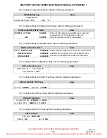
Document 190-01007-B1, latest revision. Modify the installed GTN 650 configuration
settings in accordance with the applicable figure reference listed below.
(1)
Main SW V5.00: refer to Figure 8-2.
(2)
Main SW V6.41 (or later FAA-approved versions): refer to Figure 8-4.
B. If the returned GTN 650 is used as the ADS-B Out position source, perform the following:
(1)
GTX 330ES: Verify the ADS-B Out function in accordance with Chapter 7, Section
4-1-7.
(2)
GTX 345: Verify the ADS-B Out function in accordance with Chapter 13, Section 4-
1-6, C.
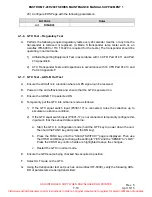
C. Optional fuel management system interface: Configure a replacement Miniflo-L (Shadin)
in accordance with Figure 8-3 (refer also to the Miniflo-L Operating Manual, Document
Number OP91204E for data entry and functional test procedures).
D. If required, refer to the applicable chapter within this supplement for the configuration set-
up procedures associated with other equipment interfaced with the GTN 650.
4-1-5. Software
Update
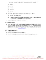
A. Verify the software version number matches the approved software version listed in
Enstrom Rotorcraft Flight Manual Supplement 28-AC-069. The software version will
appear on the start-up screen after power up. If the replaced unit does not have the
approved version of software installed, software can be downloaded from the Garmin
Dealer Resource Center at
www.flyGarmin.com
.
4-2.
Figures and Diagrams
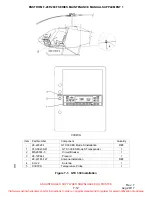
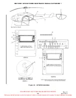
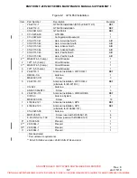
A. The GTN 650 installation is shown in Figure 8-1.
B. Configuration set-up pages: refer to paragraph 4-1-4, A, and 4-4-4, C.
C. The GTN 650 wiring interface is shown in Diagram 8-1.
D. The GTN 650/fuel management wiring interface is shown in Diagram 8-2.
Visit www.enstromhelicopter.com for instructions to order an original manual and to register for email notification of updates.

