UNCONTROLLED COPY WHEN DOWNLOADED OR PRINTED
ENSTROM F-28F/280F SERIES MAINTENANCE MANUAL SUPPLEMENT 1
Rev.
3
5-5
Nov
11/11
4-1-4. Installation
CAUTION
The attitude indicator and directional gyro are delicate electro-
mechanical instruments, which must be handled with care.
Rough handling can result in damage to the instrument and
reduce performance and life of the instrument.
A. Install the gyro unit(s) in accordance with Paragraph 7-18.A Steps (5) through (7) of
the maintenance manual.
NOTE
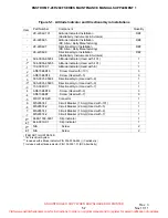
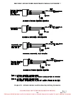
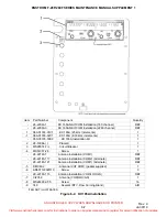
See Figure 5-1 of this supplement for gyro location in the
instrument panel.
B. Attitude indicator only:
1) Ensure that the aircraft is on a level surface.
2) Verify that the ball in the slip indicator comes to rest between the lubber lines when
viewed straight on. Check the slip indicator ball level with a reference level tool (“L”
bubble or equivalent). Place the reference tool on the aircraft floor or place the “L”
bubble on the lip of the bezel at the bottom of the slip indicator glass, as
appropriate. Adjust the slip indicator ball to correspond with the ball position in the
reference level tool.
C. Attitude indicator only: If required, install the slip indicator.
NOTE
For P/N 6648-1009-0901 slip indicator (Castleberry), refer to the
Field Replacement or Installation of Inclinometer procedure
(ref. Table 5-1).
1) Position the slip indicator housing such that the ball is centered between the lubber
lines. Install screws and tighten until snug.
2) Check the bubble level in accordance with 4-1-4.B.
3) Tighten the screws to 2 to 4 in-lbs/0.23-0.45 Nm.
D. Apply power to the gyro(s). Check that the OFF flag moves out of view and lighting is
working properly.
NOTE
The flag on the Castleberry instrument will not retract until the
gyroscope is up to operational speed. This may take up to two
minutes. The flag on the RC Allen instrument will retract as
soon as adequate power is applied.
Visit www.enstromhelicopter.com for instructions to order an original manual and to register for email notification of updates.


