UNCONTROLLED COPY WHEN DOWNLOADED OR PRINTED
ENSTROM F-28F/280F SERIES MAINTENANCE MANUAL SUPPLEMENT 1
Rev.
3
5-6
Nov
11/11
4-2. Wiring
Harnesses/Connectors
A. Inspect the plugs, connectors and receptacles for security, contact corrosion,
damaged contacts, broken wires, faulty contacts, insert cracks, and faulty insulation.
B. Inspect the leads and wiring for loose terminals, chafing, corrosion or deteriorated
condition, faulty or damaged insulation, excessive mechanical stress, broken strands, damaged
shielding, shorted shielding, routing and mounting conditions.
4-3.
Figures and Diagrams
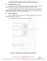
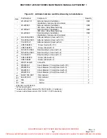
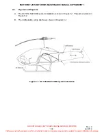
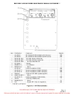
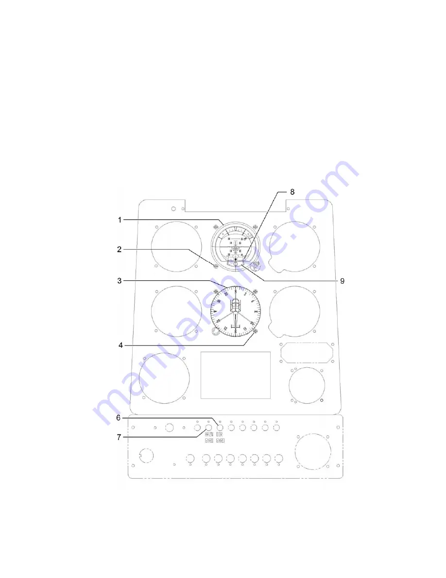
A. The installation locations and parts of the attitude indicator and directional gyro
configurations are shown in Figure 5-1.
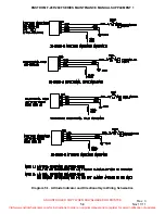
B. The configuration wiring interfaces are shown in Diagram 5-1.
Figure 5-1. Attitude Indicator and Directional Gyro Installations
Visit www.enstromhelicopter.com for instructions to order an original manual and to register for email notification of updates.


