UNCONTROLLED COPY WHEN DOWNLOADED OR PRINTED
ENSTROM F-28F/280F SERIES MAINTENANCE MANUAL SUPPLEMENT 1
Rev.
3
5-1
Nov
11/11
CHAPTER 5
ATTITUDE INDICATOR AND DIRECTIONAL GYRO
SECTION 1
SYSTEM DESCRIPTION
1-1. System
Description
A. The Attitude Indicator Installation, P/N 28-22062-( ), provides an indication of the
aircraft’s attitude relative to the earth by means of an electrically powered gyroscope. The unit is
mounted in the instrument panel. Power to the attitude indicator is provided via the
HRZN GYRO
circuit breaker (CB23) located on the left side of the center pedestal. This installation consists of
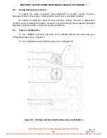
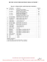
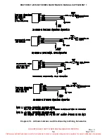
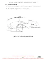
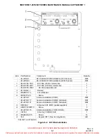
several configurations depending on the manufacturer (refer to Figure 5-1).
B. The Directional Gyro Installation, P/N 28-22062-( ), provides a heading indication
displayed on a rotating compass card by means of an electrically powered gyroscope. The unit is
mounted in the instrument panel. Power to the directional gyro is provided via the
DIR GYRO
circuit breaker (CB24) located on the left side of the center pedestal. This installation consists of
several configurations depending on the manufacturer (refer to Figure 5-1).
C. Each gyro contains internal lighting and a power monitor indication. The attitude
indicator contains a slip indicator attached to the base of the display bezel.
1-2. Vendor
Manuals
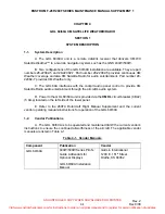
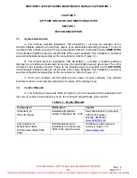
A. The following components listed in Table 5-1 are to be operated and maintained I/A/W
the current vendor’s instructions to ensure the continued airworthiness of the aircraft.
Table 5-1. Vendor Manuals
Component Publication Vendor
Attitude Gyro
RCA 26 Series
Installation/Operation
Guide, Publication No. 1403
Kelly Manufacturing Company
555 South Topeka
Wichita, KS 67202
www.kellymfg.com
Slip Indicator for
Model 300-14E(L)
Part Number 6648-1009-
0901
Field Replacement or
Installation of Inclinometer,
0050-1002, latest revision
Castleberry Instruments &
Avionics, Austin, TX
www.ciamfg.com
Visit www.enstromhelicopter.com for instructions to order an original manual and to register for email notification of updates.

