background image

UNCONTROLLED COPY WHEN DOWNLOADED OR PRINTED

   Rev. 

 i 

Jan 

15/19 


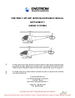
ENSTROM F-28F/280F SERIES MAINTENANCE MANUAL 

SUPPLEMENT 1 

AVIONIC SYSTEMS 


For FAA approval, the Airworthiness Limitations Section is FAA approved and specifies 
inspections and other maintenance required under 14 CFR §§ 43.16 and 91.403 of the 
Federal Aviation Regulations unless an alternative program has been FAA approved. 

For EASA approval, the Airworthiness Limitations Section is approved and variations 
must also be approved. 

Copyright 2008-2018 by 

The Enstrom Helicopter Corporation 

2209 22

nd

 Street 

Menominee, Michigan 49858-3515 


Telephone:  906-863-1200 

Fax:  906-863-6821 

Visit www.enstromhelicopter.com for instructions to order an original manual and to register for email notification of updates.

Содержание F-280F Series

Страница 1: ...3 16 and 91 403 of the Federal Aviation Regulations unless an alternative program has been FAA approved For EASA approval the Airworthiness Limitations Section is approved and variations must also be approved Copyright 2008 2018 by The Enstrom Helicopter Corporation 2209 22nd Street Menominee Michigan 49858 3515 Telephone 906 863 1200 Fax 906 863 6821 Visit www enstromhelicopter com for instructio...

Страница 2: ... PRINTED ENSTROM F 28F 280F SERIES MAINTENANCE MANUAL SUPPLEMENT 1 Rev 3 ii Nov 11 11 INTENTIONALLY LEFT BLANK Visit www enstromhelicopter com for instructions to order an original manual and to register for email notification of updates ...

Страница 3: ...pinion of the user any information has been omitted or requires clarification please direct your comments to Enstrom via this form duplicate or other similar form Send the recommended changes to The Enstrom Helicopter Corporation 2209 22nd Street Menominee MI 49858 3515 ATTN Technical Publications Manual Identification Enstrom F 28F 280F Series Maintenance Manual Supplement 1 Manual Date November ...

Страница 4: ...R PRINTED ENSTROM F 28F 280F SERIES MAINTENANCE MANUAL SUPPLEMENT 1 Rev 4 iv Jan 9 14 INTENTIONALLY LEFT BLANK Visit www enstromhelicopter com for instructions to order an original manual and to register for email notification of updates ...

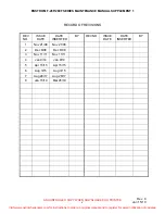
Страница 5: ... DATE DATE INSERTED BY REV NO ISSUE DATE DATE INSERTED BY 1 Nov 21 08 Nov 21 08 2 Dec 8 08 Dec 8 08 3 Nov 11 11 Nov 11 11 4 Jan 9 14 Jan 9 14 5 Apr 15 15 Apr 15 15 6 Aug 3 15 Aug 3 15 7 Aug 28 17 Aug 28 17 8 Jan 15 19 Mar 26 19 Visit www enstromhelicopter com for instructions to order an original manual and to register for email notification of updates ...

Страница 6: ... PRINTED ENSTROM F 28F 280F SERIES MAINTENANCE MANUAL SUPPLEMENT 1 Rev 8 vi Jan 15 19 INTENTIONALLY LEFT BLANK Visit www enstromhelicopter com for instructions to order an original manual and to register for email notification of updates ...

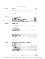
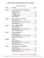
Страница 7: ... System Description 1 1 Airworthiness Limitations 1 2 Servicing 1 3 Troubleshooting 1 3 Periodic Inspections 1 3 System Maintenance 1 4 Electrical Diagram 1 7 Chapter 2 Sandia SAE5 35 Altitude Data System System Description 2 1 Airworthiness Limitations 2 2 Servicing 2 3 Troubleshooting 2 3 Periodic Inspections 2 3 System Maintenance 2 4 Electrical Diagram 2 7 Chapter 3 Garmin GNS 430W 530W GPS WA...

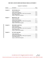
Страница 8: ...ess Limitations 6 2 Servicing Troubleshooting and Periodic Inspections 6 3 System Maintenance 6 4 Figures and Electrical Diagrams 6 5 Chapter 7 GTX 330 with ADS B Out System Description 7 1 Airworthiness Limitations 7 2 Servicing Troubleshooting and Periodic Inspections 7 3 System Maintenance 7 5 Figures and Electrical Diagrams 7 11 Chapter 8 GTN 650 System Description 8 1 Airworthiness Limitation...

Страница 9: ...ervicing Troubleshooting and Periodic Inspections 11 2 System Maintenance 11 3 Figures and Electrical Diagrams 11 3 Chapter 12 GMA 350Hc Audio Panel System Description 12 1 Airworthiness Limitations 12 2 Servicing Troubleshooting and Periodic Inspections 12 3 System Maintenance 12 4 Figures and Electrical Diagrams 12 5 Chapter 13 GTX 345 Transponder System Description 13 1 Airworthiness Limitation...

Страница 10: ...R PRINTED ENSTROM F 28F 280F SERIES MAINTENANCE MANUAL SUPPLEMENT 1 Rev 8 x Jan 15 19 INTENTIONALLY LEFT BLANK Visit www enstromhelicopter com for instructions to order an original manual and to register for email notification of updates ...

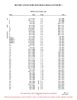
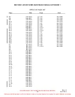
Страница 11: ...5 Dec 8 08 3 6 Dec 8 08 3 7 Dec 8 08 3 8 Dec 8 08 4 1 Dec 8 08 4 2 Nov 11 11 4 3 Dec 8 08 4 4 Dec 8 08 4 5 Dec 8 08 4 6 Dec 8 08 4 7 Dec 8 08 4 8 Dec 8 08 5 1 Nov 11 11 5 2 Nov 11 11 5 3 Nov 11 11 5 4 Nov 11 11 5 5 Nov 11 11 5 6 Nov 11 11 5 7 Nov 11 11 5 8 Nov 11 11 6 1 Jan 9 14 6 2 Jan 9 14 6 3 Jan 9 14 6 4 Jan 9 14 6 5 Jan 9 14 6 6 Jan 9 14 6 7 Jan 9 14 6 8 Jan 9 14 6 9 Jan 9 14 6 10 Jan 9 14 7 ...

Страница 12: ... 28 17 10 5 Aug 28 17 10 6 Aug 28 17 10 7 Aug 28 17 10 8 Aug 28 17 10 9 Aug 28 17 10 10 Aug 28 17 10 11 Aug 28 17 10 12 Aug 28 17 11 1 Aug 28 17 11 2 Aug 28 17 11 3 Aug 28 17 11 4 Aug 28 17 11 5 Aug 28 17 11 6 Aug 28 17 11 7 Aug 28 17 11 8 Aug 28 17 11 9 Jan 15 19 11 10 Jan 15 19 12 1 Jan 15 19 12 2 Jan 15 19 12 3 Jan 15 19 12 4 Jan 15 19 12 5 Jan 15 19 12 6 Jan 15 19 12 7 Jan 15 19 12 8 Jan 15 19...

Страница 13: ...a System 28 22090 SL30 28 22069 1 Aircraft Effectivity A The data presented in this F 28F 280F Series Maintenance Manual Supplement is applicable to all Enstrom F 28F and 280F series model helicopters Supplemental Changes and Revisions A Subsequent to the publication of the initial issue of this supplement changes in the avionics equipment support concepts and procedures as well as information dev...

Страница 14: ...date 3 Service Instructions Used to provide the owner operator and or maintenance personnel with information that is applicable to specific aircraft and does not meet the criteria of a Service Information Letter or Service Directive Bulletin Service Instructions will not be distributed to the entire fleet Service Information Letters and Service Directive Bulletins incorporated into the maintenance...

Страница 15: ... CAUTION and NOTE are used to draw attention to instructions or information deserving special consideration B WARNING Calls attention to use of materials processes methods procedures or limits that must be followed to avoid injury to personnel C CAUTION Calls attention to methods and procedures that must be followed to avoid damage to equipment D NOTE Calls attention to information essential to hi...

Страница 16: ...RINTED ENSTROM F 28F 280F SERIES MAINTENANCE MANUAL SUPPLEMENT 1 Rev 7 INTRO 4 Aug 28 17 INTENTIONALLY LEFT BLANK Visit www enstromhelicopter com for instructions to order an original manual and to register for email notification of updates ...

Страница 17: ...of the SL30 system include the panel mounted SL30 unit and nav and com antennas The SL30 provides output to a VOR LOC GS Indicator and to either a VOX ICS or an audio panel D Power to the SL30 unit is provided via the COM circuit breaker CB27 5 Amp and the NAV circuit breaker CB39 2 Amp located on the left side of the center pedestal E Refer to the 280FX Rotorcraft Flight Manual Supplement and the...

Страница 18: ...orthiness Limitations Section is FAA approved and specifies inspections and other maintenance required under 14 CFR 43 16 and 91 403 of the Federal Aviation Regulations unless an alternative program has been FAA approved B All components of the SL30 system are on condition Visit www enstromhelicopter com for instructions to order an original manual and to register for email notification of updates...

Страница 19: ...ems with the SL30 3 3 Periodic Inspections A The following inspection checklist is intended as a guide for 100 hour annual inspections for aircraft operating under normal conditions More frequent inspections may be required should adverse operating conditions be encountered Date Signature Aircraft Registration Number Aircraft Serial Number SL30 NAV COM INITIAL EACH ITEM AFTER ACCOMPLISHMENT Inspec...

Страница 20: ...circuit breaker system B The SL30 is mounted in a tray in the radio panel of the console Using a 3 32 hex driver turn the cam lock to release the unit from the tray Pull the SL30 unit from the radio panel 4 1 2 Inspection Repair SL30 A Inspect the condition and security of the tray and electrical interface B Inspect the condition and security of electrical cables C Repair procedures are not availa...

Страница 21: ...rt cracks and faulty insulation B Inspect the leads and wiring for loose terminals chafing corrosion or deteriorated condition faulty or damaged insulation excessive mechanical stress broken strands damaged shielding shorted shielding routing and mounting conditions 4 2 3 Repair Wiring Harnesses Connectors SL30 A Tighten lose terminal connectors mounting hardware and electrical component attachmen...

Страница 22: ... OR PRINTED ENSTROM F 28F 280F SERIES MAINTENANCE MANUAL SUPPLEMENT 1 1 6 Nov 18 08 INTENTIONALLY LEFT BLANK Visit www enstromhelicopter com for instructions to order an original manual and to register for email notification of updates ...

Страница 23: ...TED ENSTROM F 28F 280F SERIES MAINTENANCE MANUAL SUPPLEMENT 1 Diagram 1 1 SL30 Sheet 1 of 1 Nov 18 08 1 7 1 8 Blank Visit www enstromhelicopter com for instructions to order an original manual and to register for email notification of updates ...

Страница 24: ...UNCONTROLLED COPY WHEN DOWNLOADED OR PRINTED Visit www enstromhelicopter com for instructions to order an original manual and to register for email notification of updates ...

Страница 25: ...ion and P N 28 22090 3 is the standard system with the Altitude In Flight Monitoring function D Power to the Sandia SAE5 35 encoder is provided via the ENCDR circuit breaker CB 2 Amp located on the lower left side of the center pedestal E Refer to the 280FX Rotorcraft Flight Manual Supplement and the current vendor operating manuals instructions for operation of the Sandia SAE5 35 altitude data sy...

Страница 26: ...ness Limitations Section is FAA approved and specifies inspections and other maintenance required under 14 CFR 43 16 and 91 403 of the Federal Aviation Regulations unless an alternative program has been FAA approved B All components of the Sandia SAE5 35 system are on condition Visit www enstromhelicopter com for instructions to order an original manual and to register for email notification of up...

Страница 27: ...andia SAE5 35 3 2 Troubleshooting A No troubleshooting guidelines are available for the Sandia SAE5 35 3 3 Periodic Inspections A The following inspection checklist is intended as a guide for 100 hour annual inspections for aircraft operating under normal conditions More frequent inspections may be required should adverse operating conditions be encountered Date Signature Aircraft Registration Num...

Страница 28: ...around the circuit breaker system B The Sandia SAE5 35 is installed onto a tray mounted on a back panel bracket inside the pedestal C Disconnect the electrical cables D Slide the unit out of the tray 4 1 2 Inspection Repair Sandia SAE5 35 A Inspect the condition and security of the mounting bracket and electrical interface B Inspect the condition and security of electrical cables C Repair procedur...

Страница 29: ...nsert cracks and faulty insulation B Inspect the leads and wiring for loose terminals chafing corrosion or deteriorated condition faulty or damaged insulation excessive mechanical stress broken strands damaged shielding shorted shielding routing and mounting conditions 4 2 3 Repair Wiring Harnesses Connectors Sandia SAE5 35 A Tighten lose terminal connectors mounting hardware and electrical compon...

Страница 30: ... PRINTED ENSTROM F 28F 280F SERIES MAINTENANCE MANUAL SUPPLEMENT 1 Rev 1 2 6 Nov 21 08 INTENTIONALLY LEFT BLANK Visit www enstromhelicopter com for instructions to order an original manual and to register for email notification of updates ...

Страница 31: ...ROM F 28F 280F SERIES MAINTENANCE MANUAL SUPPLEMENT 1 Diagram 2 1 Sandia SAE5 35 Sheet 1 of 1 Rev 1 Nov 21 08 2 7 2 8 Blank Visit www enstromhelicopter com for instructions to order an original manual and to register for email notification of updates ...

Страница 32: ...UNCONTROLLED COPY WHEN DOWNLOADED OR PRINTED Visit www enstromhelicopter com for instructions to order an original manual and to register for email notification of updates ...

Страница 33: ...ower panel mounted C The 430W 530W provides optional output to a VOR LOC GS Indicator and to either a VOX ICS or an audio panel D Power to the 430W 530W unit is provided via the COMM NAV GPS 28 22037 5 or 28 22050 5 or the COMM GPS 28 22037 7 or 28 22050 7 circuit breaker CB40 5 Amp and the COMM TX circuit breaker CB41 5 Amp located on the left side of the lower panel E Refer to the 280FX Rotorcra...

Страница 34: ...rthiness Limitations Section is FAA approved and specifies inspections and other maintenance required under 14 CFR 43 16 and 91 403 of the Federal Aviation Regulations unless an alternative program has been FAA approved B All components of the GNS 430W 530W are on condition Visit www enstromhelicopter com for instructions to order an original manual and to register for email notification of update...

Страница 35: ...e displayed on the 430W 530W consult the Troubleshooting section contained in the applicable installation manual listed under reference documentation in Table 3 1 3 4 Periodic Maintenance Inspections A The following inspection checklist is intended as a guide for 100 hour annual inspections for aircraft operating under normal conditions More frequent inspections may be required should adverse oper...

Страница 36: ...ery Replacement A The 430W 530W has an internal keep alive battery that will last about 10 years The battery is used for GPS system information Regular planned replacement is not necessary The 430W 530W will display a low battery message when replacement is required Once the low battery message is displayed the battery should be replaced within 1 to 2 months B If the battery is not replaced and be...

Страница 37: ...ol counterclockwise until the unit is forced out about 3 8 inch and can be freely pulled from the rack C Slide the unit out of the tray 4 1 2 Inspection Repair GNS 430W 530W A Inspect the condition and security of the mounting bracket and electrical interface B Inspect the condition and security of electrical cables C Repair procedures are not available for the 430W 530W unit 4 1 3 Installation GN...

Страница 38: ... insert cracks and faulty insulation B Inspect the leads and wiring for loose terminals chafing corrosion or deteriorated condition faulty or damaged insulation excessive mechanical stress broken strands damaged shielding shorted shielding routing and mounting conditions 4 2 3 Repair Wiring Harnesses Connectors GNS 430W 530W A Tighten lose terminal connectors mounting hardware and electrical compo...

Страница 39: ...TROM F 28F 280F SERIES MAINTENANCE MANUAL SUPPLEMENT 1 Diagram 3 1 GNS 430W 530W Sheet 1 of 1 Rev 2 Dec 8 08 3 7 3 8 Blank Visit www enstromhelicopter com for instructions to order an original manual and to register for email notification of updates ...

Страница 40: ...UNCONTROLLED COPY WHEN DOWNLOADED OR PRINTED Visit www enstromhelicopter com for instructions to order an original manual and to register for email notification of updates ...

Страница 41: ...vide XM Satellite Radio audio entertainment through the aircraft s audio system D Power to the GDL 69 69A unit is provided via the XM DL circuit breaker CB42 5 Amp located on the left side of the lower panel E Refer to the 280FX Rotorcraft Flight Manual Supplement and the current vendor operating manuals instructions for operation of the GDL 69 69A 1 2 Vendor Publications A The GDL 69 69A is to be...

Страница 42: ...worthiness Limitations Section is FAA approved and specifies inspections and other maintenance required under 14 CFR 43 16 and 91 403 of the Federal Aviation Regulations unless an alternative program has been FAA approved B All components of the GDL 69 69A are on condition Visit www enstromhelicopter com for instructions to order an original manual and to register for email notification of updates...

Страница 43: ... Inspections A The following inspection checklist is intended as a guide for 100 hour annual inspections for aircraft operating under normal conditions More frequent inspections may be required should adverse operating conditions be encountered Date Signature Aircraft Registration Number Aircraft Serial Number GARMIN GDL 69 69A INITIAL EACH ITEM AFTER ACCOMPLISHMENT Inspect the following items eve...

Страница 44: ...or other similar device around the circuit breaker system B The GDL 69 69A is installed onto a tray mounted in the forward end of the tailcone C Disconnect the electrical cables D Slide the unit out of the tray 4 1 2 Inspection Repair GDL 69 69A A Inspect the condition and security of the mounting bracket and electrical interface B Inspect the condition and security of electrical cables C Repair p...

Страница 45: ...1 for the GDL 69 69A wiring interface B Remove the attaching hardware clamps connectors leads or wiring C Identify the connectors leads or wiring D Remove the component 4 2 2 Inspection Wiring Harnesses Connectors GDL 69 69A A Inspect the plugs connectors and receptacles for security contact corrosion damaged contacts broken wires faulty contacts insert cracks and faulty insulation B Inspect the l...

Страница 46: ... B Install the electrical component and secure with attaching hardware clamps or cable ties C Verify the GDL 69 69A operation by viewing the XM Satellite information on the GNS 430W 530W or applicable display unit or by checking the XM Information or XM Status page on the GNS 430W 530W or applicable display unit Visit www enstromhelicopter com for instructions to order an original manual and to re...

Страница 47: ...NSTROM F 28F 280F SERIES MAINTENANCE MANUAL SUPPLEMENT 1 Diagram 4 1 GDL 69 69A Sheet 1 of 1 Rev 2 Dec 8 08 4 7 4 8 Blank Visit www enstromhelicopter com for instructions to order an original manual and to register for email notification of updates ...

Страница 48: ...UNCONTROLLED COPY WHEN DOWNLOADED OR PRINTED Visit www enstromhelicopter com for instructions to order an original manual and to register for email notification of updates ...

Страница 49: ...ional gyro is provided via the DIR GYRO circuit breaker CB24 located on the left side of the center pedestal This installation consists of several configurations depending on the manufacturer refer to Figure 5 1 C Each gyro contains internal lighting and a power monitor indication The attitude indicator contains a slip indicator attached to the base of the display bezel 1 2 Vendor Manuals A The fo...

Страница 50: ...orthiness Limitations Section is FAA approved and specifies inspections and other maintenance required under 14 CFR 43 16 and 91 403 of the Federal Aviation Regulations unless an alternative program has been FAA approved B All components of the gyro systems are on condition Visit www enstromhelicopter com for instructions to order an original manual and to register for email notification of update...

Страница 51: ...tions 3 3 Periodic Inspections A The following inspection checklist is intended as a guide for 100 hour annual inspections for aircraft operating under normal conditions More frequent inspections may be required should adverse operating conditions be encountered Date Signature Aircraft Registration Number Aircraft Serial Number ATTITUDE INDICATOR AND OR DIRECTIONAL GYRO INITIAL EACH ITEM AFTER ACC...

Страница 52: ... 4 1 1 Removal CAUTION The attitude indicator and directional gyro are delicate electro mechanical instruments which must be handled with care Rough handling can result in damage to the instrument and reduce performance and life of the instrument A Remove the appropriate gyro in accordance with Paragraph 7 18 A Steps 1 through 4 of the maintenance manual B Attitude indicator only Remove the slip i...

Страница 53: ... the L bubble on the lip of the bezel at the bottom of the slip indicator glass as appropriate Adjust the slip indicator ball to correspond with the ball position in the reference level tool C Attitude indicator only If required install the slip indicator NOTE For P N 6648 1009 0901 slip indicator Castleberry refer to the Field Replacement or Installation of Inclinometer procedure ref Table 5 1 1 ...

Страница 54: ...rrosion or deteriorated condition faulty or damaged insulation excessive mechanical stress broken strands damaged shielding shorted shielding routing and mounting conditions 4 3 Figures and Diagrams A The installation locations and parts of the attitude indicator and directional gyro configurations are shown in Figure 5 1 B The configuration wiring interfaces are shown in Diagram 5 1 Figure 5 1 At...

Страница 55: ...1 2 AN515B6R16 Screw Used with 101 3 2 AN515B6R14 Screw Used with 5 3 3 505 0001 95604 Directional Gyro Used with 9 1 3 505 0001 95603 Directional Gyro Used with 9 1 3 103 0022 01 Directional Gyro Used with 7 1 4 AN515B6R16 Screw Used with 9 3 4 AN515B6R7 Screw Used with 7 3 5 MS3116F8 4S Connector 1 6 MS26574 1 Circuit Breaker 1 Amp Used with 101 1 6 MS26574 2 Circuit Breaker 2 Amp Used with 5 1 ...

Страница 56: ...280F SERIES MAINTENANCE MANUAL SUPPLEMENT 1 Rev 3 5 8 Nov 11 11 Diagram 5 1 Attitude Indicator and Directional Gyro Wiring Schematics Visit www enstromhelicopter com for instructions to order an original manual and to register for email notification of updates ...

Страница 57: ...a the COM1 NAV1 or COM2 NAV2 circuit breaker CB35 7 A located on the upper left side of the center pedestal D Refer to the Rotorcraft Flight Manual Supplement for operation of the KX 165A 1 2 Vendor Manuals A The following component listed in Table 6 1 is to be operated and maintained I A W the current vendor s instructions to ensure the continued airworthiness of the aircraft Table 6 1 Vendor Man...

Страница 58: ...ess Limitations Section is FAA approved and specifies inspections and other maintenance required under 14 CFR 43 16 and 91 403 of the Federal Aviation Regulations unless an alternative program has been FAA approved B All components of the KX 165A NAV COM system are on condition Visit www enstromhelicopter com for instructions to order an original manual and to register for email notification of up...

Страница 59: ... checklist is intended as a guide for 100 hour annual inspections for aircraft operating under normal conditions More frequent inspections may be required should adverse operating conditions be encountered Date Signature Aircraft Registration Number Aircraft Serial Number KX 165A NAV COM INITIAL EACH ITEM AFTER ACCOMPLISHMENT Inspect the following items every 100 hours or annually INITIAL 1 Inspec...

Страница 60: ...n the locking screw counterclockwise using a 3 32 Allen wrench until the unit disengages from the mounting rack C Pull the unit out of the mounting rack by pulling on the metal tabs located behind the front panel on each side of the unit 4 1 2 Inspection A Inspect the KX 165A in accordance with Paragraph 7 19 of the maintenance manual 4 1 3 Repair A Replace the KX 165A if the cover glass is loose ...

Страница 61: ...tacts broken wires faulty contacts insert cracks and faulty insulation B Inspect the leads and wiring for loose terminals chafing corrosion or deteriorated condition faulty or damaged insulation excessive mechanical stress broken strands damaged shielding shorted shielding routing and mounting conditions 4 2 3 Repair Wiring Harnesses Connectors A Tighten lose terminal connectors mounting hardware ...

Страница 62: ...agrams A The KX 165A NAV COM system installation is shown in Figure 6 1 The parts are listed in Figure 6 2 B The configuration wiring interface is shown in Diagram 6 1 Figure 6 1 KX 165A NAV COM System Installation Visit www enstromhelicopter com for instructions to order an original manual and to register for email notification of updates ...

Страница 63: ... 28 19064 Placard 1 3 MS26574 7 Circuit Breaker 1 4 MS51957 26 Screw 1 28 22183 1 Antenna Installation COM1 REF 28 22183 117 Antenna Installation COM2 Alternate REF 28 22183 121 Antenna Installation COM1 Alternate REF 5 DMC63 2 Antenna VHF COM gasket supplied 1 6 AN507C 832R10 Screw 3 28 22183 115 Antenna Installation VOR LOC GS REF 7 CI205 3 Antenna VOR LOC GS 1 8 MS24693 C55 Screw 16 9 748 Seala...

Страница 64: ... PRINTED ENSTROM F 28F 280F SERIES MAINTENANCE MANUAL SUPPLEMENT 1 Rev 4 6 8 Jan 9 14 INTENTIONALLY LEFT BLANK Visit www enstromhelicopter com for instructions to order an original manual and to register for email notification of updates ...

Страница 65: ...INTED ENSTROM F 28F 280F SERIES MAINTENANCE MANUAL SUPPLEMENT 1 Diagram 6 1 KX 165A Rev 4 Jan 9 14 6 9 6 10 Blank Visit www enstromhelicopter com for instructions to order an original manual and to register for email notification of updates ...

Страница 66: ...UNCONTROLLED COPY WHEN DOWNLOADED OR PRINTED Visit www enstromhelicopter com for instructions to order an original manual and to register for email notification of updates ...

Страница 67: ... squitter 1090ES 1090 MHz Integration of data from internal and external sources to transmit data as required per 14 CFR 91 227 and Pressure Altitude Broadcast Inhibit C The GTX 330 may also be interfaced to other equipment such as an audio panel or VOX ICS and an OAT probe D Power to the GTX 330 installation is provided via the XPNDR circuit breaker CB33 5 Amp located on the left side of the cent...

Страница 68: ...pecifies inspections and other maintenance required under 14 CFR 43 16 and 91 403 of the Federal Aviation Regulations unless an alternative program has been FAA approved B All components of the GTX 330 with ADS B Out system are on condition No component level overhaul is required for the GTX 330 with ADS B Out installation Visit www enstromhelicopter com for instructions to order an original manua...

Страница 69: ...mptom Recommended Action Transponder will not turn on Ensure the XPNDR circuit breaker is closed Ensure connectors are seated on transponder and transponder is seated properly in mounting rack Poor transponder performance Weak or intermittent radar contact reported by ATC Check and verify integrity of the antenna installation ground planes and coaxial cables Check for proper electrical bonding gro...

Страница 70: ...ollowing inspection checklist is intended as a guide for 100 hour annual inspections for aircraft operating under normal conditions Date Signature Aircraft Registration Number Aircraft Serial Number GTX 330 With ADS B Out INITIAL EACH ITEM AFTER ACCOMPLISHMENT Inspect the following items every 100 hours or annually INITIAL 1 Inspect the electrical wiring coaxial cables and mounts for security dama...

Страница 71: ... Replacement of the GPS position source requires that the GTX 330 be tested and shown to comply with 14 CFR Part 91 225 and 91 227 4 1 1 Cleaning A The front bezel keypad and display can be cleaned with a microfiber cloth or with a soft cotton cloth dampened with clean water DO NOT use any chemical cleaning agents Care should be taken to avoid scratching the surface of the display 4 1 2 Removal A ...

Страница 72: ...tion files deleted during the repair testing process Continue to GTX Test Section 4 1 6 and Section 4 1 7 B If a new or repaired or exchange GTX is installed the correct configuration parameters must be set per Section 4 1 5 and the correct software files must be loaded to the unit per Section 4 1 8 C When checkout procedures have been completed record the following information in appropriate airc...

Страница 73: ...fic Information Page Notes TRAFFIC MESSAGES TONE No action taken 5 Configure Display Mode Configuration Page with the following parameters DISPLAY MODE Configuration Page Notes DISPLAY MODE AUTO LEVEL 75 6 Configure Display Backlight Configuration Page with the following parameters DISPLAY BACKLIGHT Configuration Page Notes Adjust Offset to match sync to other installed equipment BKLT AUTO LVL 624...

Страница 74: ... 429 INPUT SPEED DATA CHANNEL 1 LOW OFF CHANNEL 2 LOW OFF 429 INPUT SPEED DATA CHANNEL 3 LOW OFF CHANNEL 4 OFF 429 OUTPUT DATA CHANNEL 1 OFF CHANNEL 2 OFF 11 Configure RS 232 Input Output Page with the following parameters RS 232 INPUT OUTPUT Page Notes RS232 INPUT OUTPUT For remote operation and ADS B position source from GTN 650 CHNL 1 REMOTE REMOTE CHNL 2 OFF OFF 12 Configure Operation Configur...

Страница 75: ... and enter flight ID per customer requirement SAME AS TAIL is typical in the U S SAME AS TAIL selection is not applicable to Non US customers POWER UP ENTRY AIRXXXXX CONFIG ENTRY AIRXXXXX 16 Configure GPS Configuration Page with the following parameters GPS Configuration page Notes GPS X OFST 0 GPS Y OFST 8 GPS INTEGRITY 1E 7 17 Configure Mode S Aircraft Type Page with the following parameters MOD...

Страница 76: ...he GTX is powered on C Ensure the ADS B TX is selected ON D Temporarily put the GTX into airborne mode as follows 1 If the GTX squat switch input P3301 17 is connected raise the collective up to simulate an airborne condition 2 If the GTX squat switch input P3301 17 is not connected temporarily configure this input such that the sensed data is airborne a Start the GTX in configuration mode hold th...

Страница 77: ...oftware Update A Verify the software version number matches the approved software version listed in Enstrom Rotorcraft Flight Manual Supplement 28 AC 070 The software version will appear on the start up screen after power up If the replaced unit does not have the approved version of software installed software can be downloaded from the Garmin Dealer Resource Center at www flyGarmin com 4 2 Figure...

Страница 78: ... GTX 330 ES Mode S Installation REF 1 010 00230 61 GTX 330 ES Mode S Transponder 1 2 MS26574 5 Circuit Breaker 1 3 28 19064 1 Placard 1 28 22183 127 Antenna Installation REF 4 AV 22 Antenna 1 5 C307PS Temperature Probe 1 Figure 7 1 GTX 330 Installation Visit www enstromhelicopter com for instructions to order an original manual and to register for email notification of updates ...

Страница 79: ...F 280F SERIES MAINTENANCE MANUAL SUPPLEMENT 1 Diagram 7 1 GTX 330 with ADS B Out Ref 28 19071 Rev F Rev 5 Apr 15 15 7 13 7 14 Blank Visit www enstromhelicopter com for instructions to order an original manual and to register for email notification of updates ...

Страница 80: ...UNCONTROLLED COPY WHEN DOWNLOADED OR PRINTED Visit www enstromhelicopter com for instructions to order an original manual and to register for email notification of updates ...

Страница 81: ...TENANCE MANUAL SUPPLEMENT 1 Diagram 7 2 GTX 330 with ADS B Out A 30 Altitude Digitizer Interface Ref 28 19076 1 Rev B Rev 5 Apr 15 15 7 15 7 16 Blank Visit www enstromhelicopter com for instructions to order an original manual and to register for email notification of updates ...

Страница 82: ...UNCONTROLLED COPY WHEN DOWNLOADED OR PRINTED Visit www enstromhelicopter com for instructions to order an original manual and to register for email notification of updates ...

Страница 83: ...NTENANCE MANUAL SUPPLEMENT 1 Diagram 7 3 GTX 330 with ADS B Out AA83 001 Stereo ICS Interface Ref 28 19070 101 Rev D Rev 5 Apr 15 15 7 17 7 18 Blank Visit www enstromhelicopter com for instructions to order an original manual and to register for email notification of updates ...

Страница 84: ...UNCONTROLLED COPY WHEN DOWNLOADED OR PRINTED Visit www enstromhelicopter com for instructions to order an original manual and to register for email notification of updates ...

Страница 85: ... of VOR GPS LOC and GS information 5 Fuel management system C The GTN 650 utilizes Navigation Basemap SafeTaxi Terrain and Obstacle databases for the map display A Secure Digital SD card is used to load and store various types of data For basic flight operations the SD card is required for Terrain Obstacle and SafeTaxi database storage as well as Jeppesen aviation database updates D Power to the G...

Страница 86: ...C Maintenance Manual Document No 190 01007 B1 latest revision GTN 6XX 7XX Telligence Voice Command Guide Document No 190 01007 50 latest revision SECTION 2 AIRWORTHINESS LIMITATIONS 2 1 Airworthiness Limitations A For FAA approval the Airworthiness Limitations Section is FAA approved and specifies inspections and other maintenance required under 14 CFR 43 16 and 91 403 of the Federal Aviation Regu...

Страница 87: ... 3 Periodic Inspections Maintenance A The following inspection checklist is intended as a guide for 100 hour annual inspections for aircraft operating under normal conditions More frequent inspections may be required should adverse operating conditions be encountered Date Signature Aircraft Registration Number Aircraft Serial Number GTN 650 INITIAL EACH ITEM AFTER ACCOMPLISHMENT Inspect the follow...

Страница 88: ...re should be taken to avoid scratching the surface of the display B Select the Utilities page group from the Home page then touch Clean Screen key to start Screen Cleaning Mode Touch the Home key to exit Screen Cleaning Mode 4 1 2 Removal A Remove power to the GTN 650 unit Pull the COM and NAV GPS circuit breakers out Disable the circuit breakers by installing a cable tie or other similar device a...

Страница 89: ...tion 4 1 7 2 GTX 345 Verify the ADS B Out function in accordance with Chapter 13 Section 4 1 6 C C Optional fuel management system interface Configure a replacement Miniflo L Shadin in accordance with Figure 8 3 refer also to the Miniflo L Operating Manual Document Number OP91204E for data entry and functional test procedures D If required refer to the applicable chapter within this supplement for...

Страница 90: ...NTED ENSTROM F 28F 280F SERIES MAINTENANCE MANUAL SUPPLEMENT 1 Rev 8 8 6 Jan 15 19 Figure 8 1 GTN 650 Installation Visit www enstromhelicopter com for instructions to order an original manual and to register for email notification of updates ...

Страница 91: ...ircuit Breaker 1 3 7277 5 5 5 amp Circuit Breaker 1 4 28 22183 1 Antenna Installation VHF COM 1 REF DMC63 1 A Antenna 1 MS24693 C51 Screw 3 5 28 22183 117 Antenna Installation VHF COM 2 alternate for 28 22183 1 REF C1292 1 Antenna 1 AN507 C832R10 Screw 3 6 28 22183 115 Antenna Installation VOR LOC GS REF CI205 3 Antenna System 1 MS24693 C55 Screw 16 7 4196582 121 Antenna Installation GPS REF 7 419...

Страница 92: ... PRINTED ENSTROM F 28F 280F SERIES MAINTENANCE MANUAL SUPPLEMENT 1 Rev 7 8 8 Aug 28 17 INTENTIONALLY LEFT BLANK Visit www enstromhelicopter com for instructions to order an original manual and to register for email notification of updates ...

Страница 93: ...ng Configuration Page Display Keys Source Source Lighting Bus 1 Lighting Bus 1 Minimum Level Minimum Level 5 00 5 00 Photocell Configuration Page Response Time Slope Offset 2sec 50 50 Note 1 Key Backlight Cutoff Photocell Transition 80 10 Notes 1 Adjust Offset to match sync to other installed equipment Lighting Bus Configuration Page Lighting Bus 1 28V DC Response Time Slope Offset 0sec 15 15 Note...

Страница 94: ...UNCONTROLLED COPY WHEN DOWNLOADED OR PRINTED Visit www enstromhelicopter com for instructions to order an original manual and to register for email notification of updates ...

Страница 95: ...erwise 2 Switch to 8 33 KHz prior to shipment per customer requirement Europe Asia System Alerts Note 1 Arrival Active Proximity 3 0 NM Airspace Alerts All Active Altitude Buffer 200 FT Notes 1 These settings can be modified per customer requirements unless noted otherwise System Units Note 1 Nav Angle Magnetic Temperature Celsius Fuel Gallons GAL Position Format LAT LON Notes 1 These settings can...

Страница 96: ...UNCONTROLLED COPY WHEN DOWNLOADED OR PRINTED Visit www enstromhelicopter com for instructions to order an original manual and to register for email notification of updates ...

Страница 97: ...NUMBER OF ENGINES 0 SINGLE C 0 LOW FUEL CUT OFF 0 OFF o 5 OR 0 GPS OUTPUT 5 INTERFACED TO A GARMIN GTN 650 0 OFF I 1 OR 0 GPS INPUT 1 INTERFACED TO A GARMIN GTN 650 0 OFF d 0 ENDURANCE WARNING TIME 0 45 MIN F 0 ENGINE TYPE 0 INJECTOR TURBINE u 0 IGNORE LORAN WARNINGS 0 NO s 5 LOW FUEL LEVEL 5 5 GALLONS Group 2 Configuration Page Notes o 5 OR 0 GPS OUTPUT 5 INTERFACED TO A GARMIN GTN 650 0 OFF I 1 ...

Страница 98: ...UNCONTROLLED COPY WHEN DOWNLOADED OR PRINTED Visit www enstromhelicopter com for instructions to order an original manual and to register for email notification of updates ...

Страница 99: ...NTENANCE MANUAL SUPPLEMENT 1 Figure 8 4 GTN 650 Configuration Set Up Main SW V6 41 Ref 28 19079 9 Rev G Sheet 1 of 2 Rev 8 Jan 15 19 8 15 8 16 Blank Visit www enstromhelicopter com for instructions to order an original manual and to register for email notification of updates ...

Страница 100: ...UNCONTROLLED COPY WHEN DOWNLOADED OR PRINTED Visit www enstromhelicopter com for instructions to order an original manual and to register for email notification of updates ...

Страница 101: ...NTENANCE MANUAL SUPPLEMENT 1 Figure 8 4 GTN 650 Configuration Set Up Main SW V6 41 Ref 28 19079 9 Rev G Sheet 2 of 2 Rev 8 Jan 15 19 8 17 8 18 Blank Visit www enstromhelicopter com for instructions to order an original manual and to register for email notification of updates ...

Страница 102: ...UNCONTROLLED COPY WHEN DOWNLOADED OR PRINTED Visit www enstromhelicopter com for instructions to order an original manual and to register for email notification of updates ...

Страница 103: ...F SERIES MAINTENANCE MANUAL SUPPLEMENT 1 Diagram 8 1 GTN 650 Interface Ref 28 19079 9 Rev G Sheet 1 of 2 Rev 8 Jan 15 19 8 19 8 20 Blank Visit www enstromhelicopter com for instructions to order an original manual and to register for email notification of updates ...

Страница 104: ...UNCONTROLLED COPY WHEN DOWNLOADED OR PRINTED Visit www enstromhelicopter com for instructions to order an original manual and to register for email notification of updates ...

Страница 105: ...F SERIES MAINTENANCE MANUAL SUPPLEMENT 1 Diagram 8 1 GTN 650 Interface Ref 28 19079 9 Rev G Sheet 2 of 2 Rev 8 Jan 15 19 8 21 8 22 Blank Visit www enstromhelicopter com for instructions to order an original manual and to register for email notification of updates ...

Страница 106: ...UNCONTROLLED COPY WHEN DOWNLOADED OR PRINTED Visit www enstromhelicopter com for instructions to order an original manual and to register for email notification of updates ...

Страница 107: ...IES MAINTENANCE MANUAL SUPPLEMENT 1 Diagram 8 2 GTN 650 Fuel Management System Interface Ref 28 19078 1 Rev A Rev 8 Jan 15 19 8 23 8 24 Blank Visit www enstromhelicopter com for instructions to order an original manual and to register for email notification of updates ...

Страница 108: ...UNCONTROLLED COPY WHEN DOWNLOADED OR PRINTED Visit www enstromhelicopter com for instructions to order an original manual and to register for email notification of updates ...

Страница 109: ...ped with a quick disconnect feature Installation of both port and starboard side collective sticks is identical D Refer to the applicable F 28F or 280FX Rotorcraft Flight Manual for limitations and basic operation instructions SECTION 2 AIRWORTHINESS LIMITATIONS 2 1 Airworthiness Limitations A The Airworthiness Limitations Section is FAA approved and specifies inspections and other maintenance req...

Страница 110: ... bolt 3 and washer 4 from the top of the collective stick socket 2 D Remove the collective stick 1 from the collective stick socket 2 4 1 2 Installation A Install the collective stick 1 into the collective stick socket 2 and align holes B Install washer 4 and bolt 3 Torque bolt 50 in lbs 5 7 Nm and safety wire with MS20995C32 C Connect the wire terminals for the starter button D Cycle the collecti...

Страница 111: ...ot Collective Stick Assembly chrome plated finish REF 1 28 16039 7 Starboard Copilot Collective Stick Assembly flat black finish REF 2 28 16029 3 Socket Bellcrank Assembly 1 3 28 16011 1 Bolt 1 4 AN960 516L Washer 1 MS20995C32 Safety Wire A R Figure 9 1 Starboard Copilot Dual Start Collective Stick Installation Visit www enstromhelicopter com for instructions to order an original manual and to reg...

Страница 112: ... ENSTROM F 28F 280F SERIES MAINTENANCE MANUAL SUPPLEMENT 1 Rev 5 9 4 Apr 15 15 Diagram 9 1 Dual Start Switch Interface Visit www enstromhelicopter com for instructions to order an original manual and to register for email notification of updates ...

Страница 113: ... located on the left side of the lower instrument panel console If equipped with a second transceiver unit such as the GTN 650 power is provided via the COM 1 or COM 2 circuit breaker and NAV 1 or NAV 2 circuit breaker The NAV circuit breaker may also provide power to the CDI E Refer to F 28F 280FX Rotorcraft Flight Manual Supplement 28 AC 074 for GNC 255A limitations and basic operation instructi...

Страница 114: ...iness Limitations Section is FAA approved and specifies inspections and other maintenance required under 14 CFR 43 16 and 91 403 of the Federal Aviation Regulations unless an alternative program has been FAA approved B All components of the GNC 255A installation are on condition Visit www enstromhelicopter com for instructions to order an original manual and to register for email notification of u...

Страница 115: ...on product support for assistance ref para 1 2 3 3 Periodic Inspections Maintenance A The following inspection checklist is intended as a guide for 100 hour annual inspections for aircraft operating under normal conditions More frequent inspections may be required should adverse operating conditions be encountered Date Signature Aircraft Registration Number Aircraft Serial Number GNC 255A INITIAL ...

Страница 116: ...t breakers by installing a cable tie or other similar device around each circuit breaker stem B Insert the 3 32 inch hex drive tool into access hole on the unit face Rotate the hex tool counterclockwise until the unit is forced out about 3 8 inch and the hex drive tool completely stops C Carefully pull the unit from the rack 4 1 3 Installation NOTE Do not use excessive force when inserting the GNC...

Страница 117: ... 1 5 Software Update A Verify the software version number matches the approved software version listed in Enstrom Rotorcraft Flight Manual Supplement 28 AC 074 The software version will appear on the start up screen after power up If the replaced unit does not have the approved version of software installed software can be downloaded from the Garmin Dealer Resource Center at www flyGarmin com 4 2 ...

Страница 118: ...TED ENSTROM F 28F 280F SERIES MAINTENANCE MANUAL SUPPLEMENT 1 Rev 7 10 6 Aug 28 17 Figure 10 1 GNC 255A Installation Visit www enstromhelicopter com for instructions to order an original manual and to register for email notification of updates ...

Страница 119: ...MS26574 5 Circuit Breaker 5 amp 1 28 22183 1 Antenna Installation VHF COM 1 REF 4 DMC63 1 A Antenna 1 MS24693 C51 Screw 3 28 22183 117 Antenna Installation VHF COM 2 alternate for 28 22183 1 REF 5 DMC63 1 A Antenna 1 MS24693 C51 Screw 3 28 22183 115 Antenna Installation VOR LOC GS REF 6 CI205 3 Antenna System 1 MS24693 C55 Screw 16 7 4119835 33 Placard 1 8 28 19064 1 Placard 1 9 28 19064 1 Placard...

Страница 120: ...PRINTED ENSTROM F 28F 280F SERIES MAINTENANCE MANUAL SUPPLEMENT 1 Rev 7 10 8 Aug 28 17 INTENTIONALLY LEFT BLANK Visit www enstromhelicopter com for instructions to order an original manual and to register for email notification of updates ...

Страница 121: ...F SERIES MAINTENANCE MANUAL SUPPLEMENT 1 Figure 10 2 GNC 255 Configuration Set Up Ref 28 19069 103 Rev C Rev 7 Aug 28 17 10 9 10 10 Blank Visit www enstromhelicopter com for instructions to order an original manual and to register for email notification of updates ...

Страница 122: ...UNCONTROLLED COPY WHEN DOWNLOADED OR PRINTED Visit www enstromhelicopter com for instructions to order an original manual and to register for email notification of updates ...

Страница 123: ...F 28F 280F SERIES MAINTENANCE MANUAL SUPPLEMENT 1 Diagram 10 1 GNC 255A Ref 28 19069 103 Rev C Rev 7 Aug 28 17 10 11 10 12 Blank Visit www enstromhelicopter com for instructions to order an original manual and to register for email notification of updates ...

Страница 124: ...UNCONTROLLED COPY WHEN DOWNLOADED OR PRINTED Visit www enstromhelicopter com for instructions to order an original manual and to register for email notification of updates ...

Страница 125: ...ndor Manuals A The following components listed in Table 11 1 are to be operated and maintained I A W the current vendor s instructions to ensure the continued airworthiness of the aircraft Table 11 1 Vendor Manuals Component Publication Vendor MD200 306 Installation Manual and Operating Instructions Number 8017972 latest revision Mid Continent Inst Co Inc 9400 E 34th Street N Wichita KS 67226 MD20...

Страница 126: ...TN 650 D Refer to the applicable electrical schematic when troubleshooting MD200 Series CDI interfaced to other equipment E If the MD200 Series unit fails to operate after troubleshooting efforts refer to paragraph 1 2 for the manufacturer contact information and additional assistance 3 3 Periodic Inspections Maintenance A The following inspection checklist is intended as a guide for 100 hour annu...

Страница 127: ...strom F 28F 280F Series Maintenance Manual 4 1 1 Removal A Remove the MD200 Series CDI in accordance with paragraph 7 18 A steps 1 through 4 of the F 28F 280F Series Maintenance Manual 4 1 2 Installation A Install the MD200 Series CDI in accordance with paragraph 7 18 A steps 5 through 7 of the F 28F 280F Series Maintenance Manual 4 2 Figures and Electrical Diagrams A The GTN 650 installation is s...

Страница 128: ...4 Aug 28 17 Item Part Number Description Quantity 1 MD200 306 Indicator 1 1 MD200 706 Indicator 1 2 AN515B6R14 Screw 3 2 MS35214 30 Screw alternate 3 Figure 11 1 MD200 Series Installation Visit www enstromhelicopter com for instructions to order an original manual and to register for email notification of updates ...

Страница 129: ...F SERIES MAINTENANCE MANUAL SUPPLEMENT 1 Diagram 11 1 GTN 650 MD200 306 Interface Ref 28 19067 107 Rev D Rev 7 Aug 28 17 11 5 11 6 Blank Visit www enstromhelicopter com for instructions to order an original manual and to register for email notification of updates ...

Страница 130: ...UNCONTROLLED COPY WHEN DOWNLOADED OR PRINTED Visit www enstromhelicopter com for instructions to order an original manual and to register for email notification of updates ...

Страница 131: ...F SERIES MAINTENANCE MANUAL SUPPLEMENT 1 Diagram 11 2 GNC 255A MD200 706 Interface Ref 28 19067 109 Rev E Rev 7 Aug 28 17 11 7 11 8 Blank Visit www enstromhelicopter com for instructions to order an original manual and to register for email notification of updates ...

Страница 132: ...UNCONTROLLED COPY WHEN DOWNLOADED OR PRINTED Visit www enstromhelicopter com for instructions to order an original manual and to register for email notification of updates ...

Страница 133: ...F SERIES MAINTENANCE MANUAL SUPPLEMENT 1 Diagram 11 3 GTN 650 MD200 706 Interface Ref 28 19067 109 Rev E Rev 8 Jan 15 19 11 9 11 10 Blank Visit www enstromhelicopter com for instructions to order an original manual and to register for email notification of updates ...

Страница 134: ...UNCONTROLLED COPY WHEN DOWNLOADED OR PRINTED Visit www enstromhelicopter com for instructions to order an original manual and to register for email notification of updates ...

Страница 135: ...estal A marker beacon antenna is installed on the bottom of the tailcone Table 12 1 GMA 350Hc Configuration Part Numbers Part Number Marker Beacon Receiver 28 22048 5 Yes C The GMA 350Hc may be configured with a traditional avionic system VOR LOC GS GPS NAV COM transponder etc or with the Garmin G1000H Integrated Flight Deck D Power to the audio panel is provided via the AUDIO PANEL circuit breake...

Страница 136: ...ed and specifies inspections and other maintenance required under 14 CFR 43 16 and 91 403 of the Federal Aviation Regulations unless an alternative program has been FAA approved B For EASA approval this Airworthiness Limitations Section is approved and variations must also be approved C All components of the GMA 350Hc are on condition Visit www enstromhelicopter com for instructions to order an or...

Страница 137: ...rts contact Garmin aviation product support for assistance ref para 1 2 3 3 Periodic Inspections A The following inspection checklist is intended as a guide for 100 hour annual inspections for aircraft operating under normal conditions More frequent inspections may be required should adverse operating conditions be encountered Date Signature Aircraft Registration Number Aircraft Serial Number GMA ...

Страница 138: ...el operation in accordance with paragraph 3 2 of the GMA 350 350H Audio Panel Maintenance Manual para 1 2 4 1 3 Repair A Replace the audio panel if any of the tests performed in paragraph 4 1 2 fail 4 1 4 Installation NOTE Do not use excessive force when inserting the GMA 350Hc into the rack This may damage the connectors unit and or unit rack A Insert the GMA 350Hc unit into the rack B Lock the u...

Страница 139: ... software version information is available via the configuration tool Table 12 2 or the GTN navigator system status page for interfaced equipment If the replaced unit does not have the approved version of software installed software can be downloaded from the Garmin Dealer Resource Center at www flyGarmin com 4 3 Figures and Diagrams A GMA 350Hc installation parts list Figure 12 1 and Figure 12 2 ...

Страница 140: ... GMA 350Hc 1 011 02302 00 Connector Kit Included with GMA 350Hc REF 2 7101SYZQE Switch Used with 4220672 109 1 3 8121SYZGE Push Button Switch 1 4 7277 5 5 5 amp Circuit Breaker 1 5 DMN43 1 Antenna 1 6 AN960 8L Washer 3 7 AN365 832A Nut 3 8 161 3402 E Entertainment Jack 1 Item not illustrated Figure 12 2 GMA 350Hc Installation Visit www enstromhelicopter com for instructions to order an original ma...

Страница 141: ...80F SERIES MAINTENANCE MANUAL SUPPLEMENT 1 Figure 12 3 GMA 350Hc Configuration Ref 28 19090 13 Rev D Sheet 1 of 2 Rev 8 Jan 15 19 12 7 Visit www enstromhelicopter com for instructions to order an original manual and to register for email notification of updates ...

Страница 142: ...80F SERIES MAINTENANCE MANUAL SUPPLEMENT 1 Figure 12 3 GMA 350Hc Configuration Ref 28 19090 13 Rev D Sheet 2 of 2 Rev 8 Jan 15 19 12 8 Visit www enstromhelicopter com for instructions to order an original manual and to register for email notification of updates ...

Страница 143: ...SERIES MAINTENANCE MANUAL SUPPLEMENT 1 Diagram 12 1 GMA 350Hc Interface Ref 28 19090 13 Rev D Sheet 1 of 2 Rev 8 Jan 15 19 12 9 12 10 Blank Visit www enstromhelicopter com for instructions to order an original manual and to register for email notification of updates ...

Страница 144: ...UNCONTROLLED COPY WHEN DOWNLOADED OR PRINTED Visit www enstromhelicopter com for instructions to order an original manual and to register for email notification of updates ...

Страница 145: ...ERIES MAINTENANCE MANUAL SUPPLEMENT 1 Diagram 12 1 GMA 350Hc Interface Ref 28 19090 13 Rev D Sheet 2 of 2 Rev 8 Jan 15 19 12 11 12 12 Blank Visit www enstromhelicopter com for instructions to order an original manual and to register for email notification of updates ...

Страница 146: ...UNCONTROLLED COPY WHEN DOWNLOADED OR PRINTED Visit www enstromhelicopter com for instructions to order an original manual and to register for email notification of updates ...

Страница 147: ... to transmit data as required per 14 CFR 91 227 and Pressure Altitude Broadcast Inhibit C For ADS B In system functionality the GTX receives ADS B In data on 1090 MHz and UAT 978 MHz and provides ADS B traffic information and alerting to the pilot via an optional interfaced display D The GTX 345 may also be interfaced to other equipment such as an audio panel or VOX ICS and an OAT probe E Power to...

Страница 148: ...cing should occur when an item fails to operate only after the authorized maintenance technician troubleshoots the system 3 2 Troubleshooting A Refer to GTX 345 Part 27 AML Maintenance Manual Document No 190 00734 21 Section 5 and the electrical schematic Diagram 16 1 when troubleshooting the GTX 345 installation 3 3 Periodic Inspections A Refer to GTX 345 Part 27 AML Maintenance Manual Doc No 190...

Страница 149: ...move power to the GTX 345 unit Pull the XPNDR circuit breaker out Disable the circuit breaker by installing a cable tie or other similar device around the circuit breaker stem B Insert the 3 32 inch hex drive tool into access hole on the unit face Turn the hex tool counterclockwise until the unit is forced out about 3 8 inch C Pull the unit straight out of the rack 4 1 3 GTX 345 Installation CAUTI...

Страница 150: ...screws securing the unit to the backplate 4 1 5 GAE Altitude Encoder Installation A Secure the altitude encoder to the backplate assembly with two screws torque to 8 in lb B Connect the wiring harness to the altitude encoder C Secure the static line to the altitude encoder using standard practice D Install the transponder para 4 1 3 E Remove the cable tie or other similar device from the XPNDR cir...

Страница 151: ...Perform GTX Test in accordance with GTX 345 Part 27 AML Maintenance Manual Document No 190 00734 21 Section 8 4 D When checkout procedures have been completed record the following information in appropriate aircraft maintenance logs 1 Part number and version number of any software updates performed during maintenance 2 Record part and serial number of any LRU which was replaced 4 2 Figures and Dia...

Страница 152: ...3 129 Antenna Installation REF 3 AV 74 Antenna 1 8 Split Washer 2 8 32 Hex Nut 2 No number Rubber pad 1 4 C307PS OAT Probe 1 28 19064 1 Placard ADS B IN OUT INSTALLED 1 5 4119835 33 Placard RMT XPNDR IDENT 1 6 4119835 47 Placard TRAFFIC CANCEL 1 7 011 03080 00 GAE Altitude Encoder 1 Item not illustrated Location per customer requirements Figure 13 2 GTX 345 Installation Visit www enstromhelicopter...

Страница 153: ... 280F SERIES MAINTENANCE MANUAL SUPPLEMENT 1 Figure 13 3 GTX 345 Configuration Ref 28 19071 103 Rev G Rev 8 Jan 15 19 13 7 13 8 Blank Visit www enstromhelicopter com for instructions to order an original manual and to register for email notification of updates ...

Страница 154: ...UNCONTROLLED COPY WHEN DOWNLOADED OR PRINTED Visit www enstromhelicopter com for instructions to order an original manual and to register for email notification of updates ...

Страница 155: ...F 280F SERIES MAINTENANCE MANUAL SUPPLEMENT 1 Diagram 13 1 GTX 345 Interface Ref 28 19071 103 Rev G Rev 8 Jan 15 19 13 9 13 10 Blank Visit www enstromhelicopter com for instructions to order an original manual and to register for email notification of updates ...

Страница 156: ...UNCONTROLLED COPY WHEN DOWNLOADED OR PRINTED Visit www enstromhelicopter com for instructions to order an original manual and to register for email notification of updates ...

Отзывы: