SMARC T335x Carrier Board Hardware Design Guide, Document Revision 1.2
The input
Rs
is used for mode control purpose. Both transceiver products
are powered with a nominal supply voltage of +5 V.
The
CAN
bus controller outputs a serial transmit data stream to the
TxD
input of the transceiver. An internal pull-up function sets the
TxD
input to
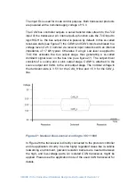
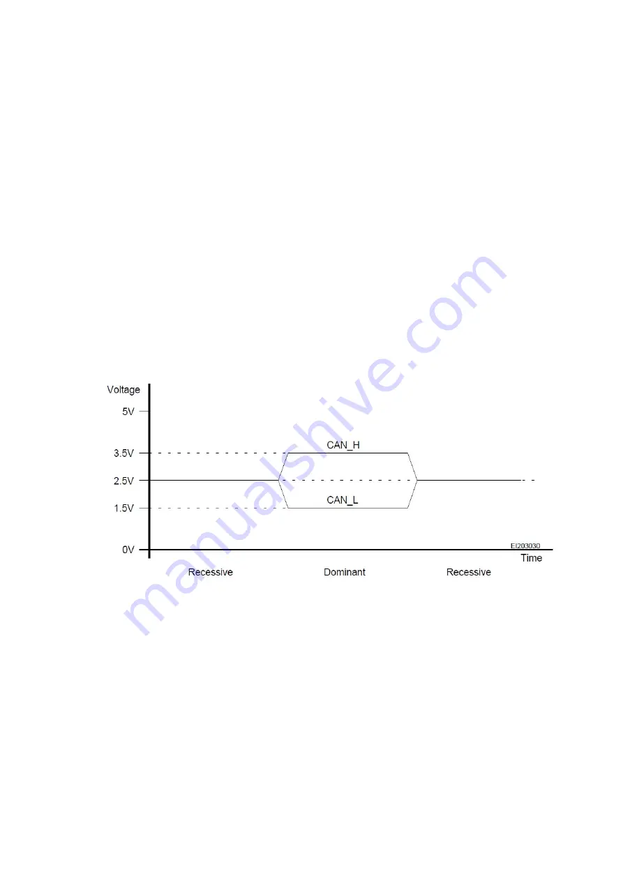
logic HIGH i.e. the bus output driver is passive by default. In this so-called
recessive state (see figure 27) the
CANH
and
CANL
inputs are biased to a
voltage level of 2.5 V nominal via receiver input networks with an internal
impedance of 17 kW typical. Otherwise if a logic Low-level is applied to
TxD
, this activates the bus output stage, thus generating a so-called
dominant signal level on the bus line (see figure 27). The output driver
consists of a source and a sink output stage.
CANH
is attached to the
source output and CANL to the sink output stage. The nominal voltage in
the dominant state is 3.5 V for the
CAN_H
line and 1.5 V for the
CAN_L
line.
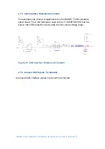
Figure 27: Nominal Bus Levels According to ISO 11898
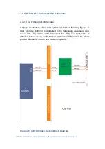
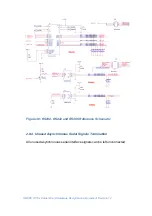
In Figure 26 the transceiver is directly connected to the protocol controller
and its application circuitry. In some highly regulated cases like in-vehicle
networking environment, galvanic isolation barriers are needed between
the high- and low-voltage parts. An isolated CAN transceiver might be
applied. Please see the application note of the used CAN transceiver for
details.
Содержание SMARC T335 Series
Страница 2: ...SMARC T335x Carrier Board Hardware Design Guide Document Revision 1 2 ...
Страница 118: ...SMARC T335x Carrier Board Hardware Design Guide Document Revision 1 2 Figure 44 Power Supply Reference Schematic ...
Страница 124: ...SMARC T335x Carrier Board Hardware Design Guide Document Revision 1 2 Figure 46 SMARC T335X Module Mechanical Outline ...

