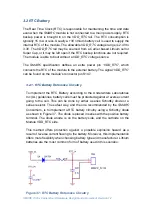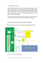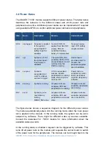
SMARC T335x Carrier Board Hardware Design Guide, Document Revision 1.2
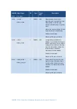
SMARC Edge Finger
I/O
Type
Power
Rail
Description
Pin#
Pin
Name
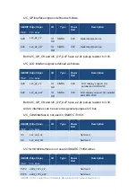
S149
SLEEP#
/
RMII2_TXD0
I
CMOS
3.3V
Sleep indicator from Carrier
board. May be sourced from user
Sleep button or Carrier logic.
Carrier to float the line in in-active
state.
Active low, level sensitive. Should
be de-bounced on the Module.
Pulled up on Module.
Driven by OD part on Carrier.
S148
LID#
/
RMII2_TXD1
I
CMOS
3.3V
Lid open/close indication to
Module. Low indicates lid closure
(which system may use to initiate
a sleep state). Carrier to float the
line in in-active state. Active low,
level sensitive. Should be
de-bounced on the Module
Pulled up on Module.
Driven by OD part on Carrier.
P128
POWER_BTN#
/
RMII2_CRS_DV
I
CMOS
3.3V
Power-button input from Carrier
board. Carrier to float the line in
in-active state. Active low, level
sensitive. It is de-bounced on the
Module
Pulled up on Module.
Driven by OD part on Carrier.
Содержание SMARC T335 Series
Страница 2: ...SMARC T335x Carrier Board Hardware Design Guide Document Revision 1 2 ...
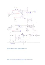
Страница 118: ...SMARC T335x Carrier Board Hardware Design Guide Document Revision 1 2 Figure 44 Power Supply Reference Schematic ...
Страница 124: ...SMARC T335x Carrier Board Hardware Design Guide Document Revision 1 2 Figure 46 SMARC T335X Module Mechanical Outline ...

