SMARC T335x Carrier Board Hardware Design Guide, Document Revision 1.2
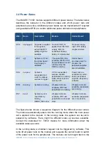
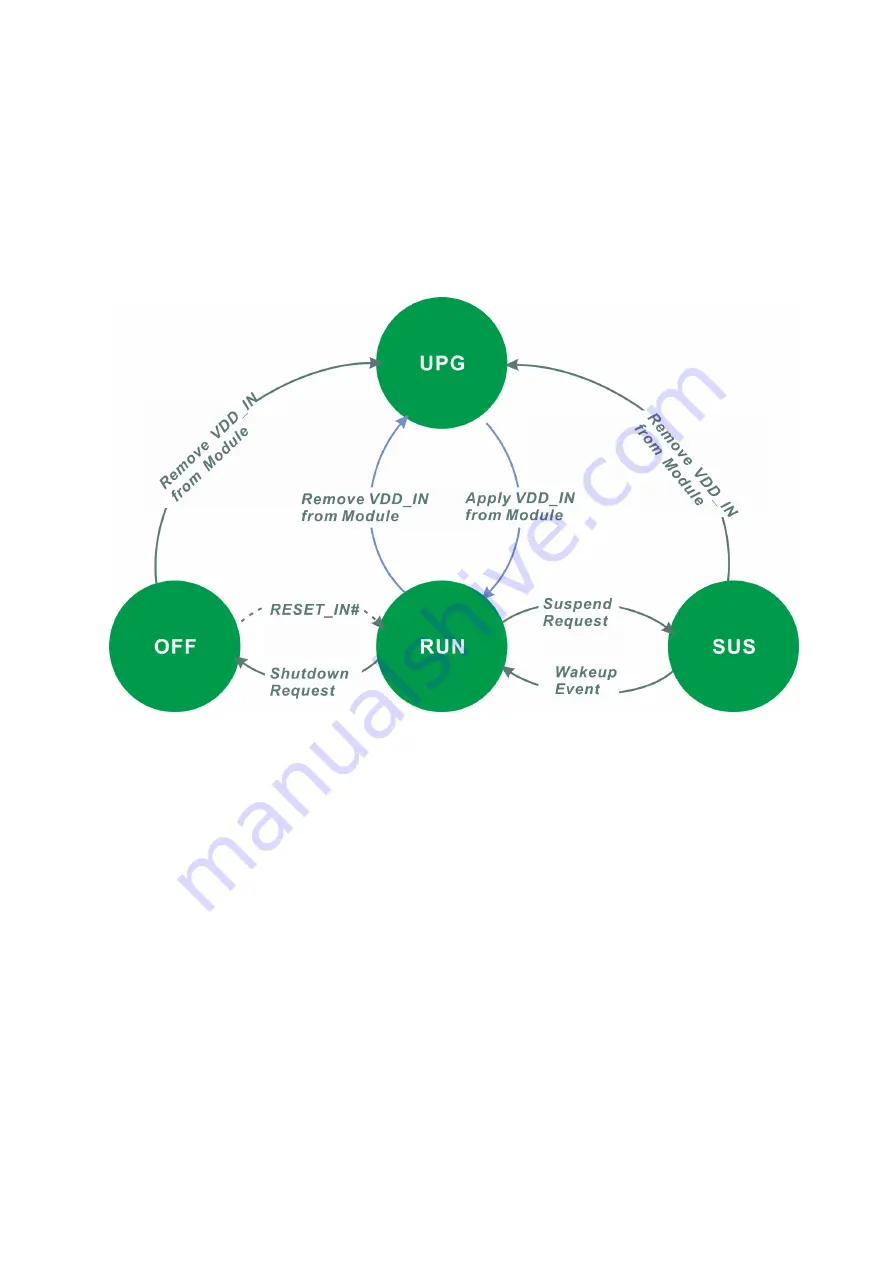
running mode in two ways. The module main voltage rail (
VDD_IN
) can be
removed and applied again. If needed, this could also be done with a button
and a small circuit.
SMARC T335X
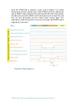
module supports being power cycled by
asserting the
RESET_IN
# signal (e.g. by pressing the reset button or shunt
and relief the reset jumper), please consult the associated module datasheet
for more information about the support power cycle methods.
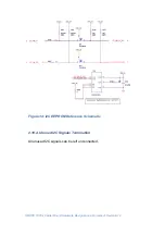
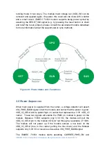
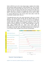
Figure 39: Power States and Transitions
3.5 Power Sequences
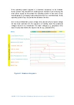
When main power is supplied from the carrier, a voltage detector will assert
VIN_PWR_BAD#
signal to tell the module and carrier that the power is good.
VDD_IO_SEL#
will be pulled high on carrier that represents a 3.3V
VDD_IO
carrier. These two signals will enable the PMIC on module to power on the
module. Because
T335X
supports only 3.3V I/O, the module will pull the
VDD_IO_SEL#
pin to the module
VDD_IN
rail through a resistance of 100K.
The module will not power up if the module senses a low level on the
VDD_IO_SEL
# (due to the carrier pulling the line down) and the Module
supports only 3.3V I/O or receives a low-active
VIN_PWR_BAD#
signal.
The
SMARC T335X
module starts asserting
CARRIER_PWR_ON
and
Содержание SMARC T335 Series
Страница 2: ...SMARC T335x Carrier Board Hardware Design Guide Document Revision 1 2 ...
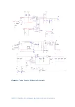
Страница 118: ...SMARC T335x Carrier Board Hardware Design Guide Document Revision 1 2 Figure 44 Power Supply Reference Schematic ...
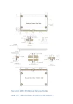
Страница 124: ...SMARC T335x Carrier Board Hardware Design Guide Document Revision 1 2 Figure 46 SMARC T335X Module Mechanical Outline ...

