
SMARC T335x Carrier Board Hardware Design Guide, Document Revision 1.2
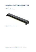
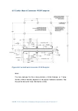
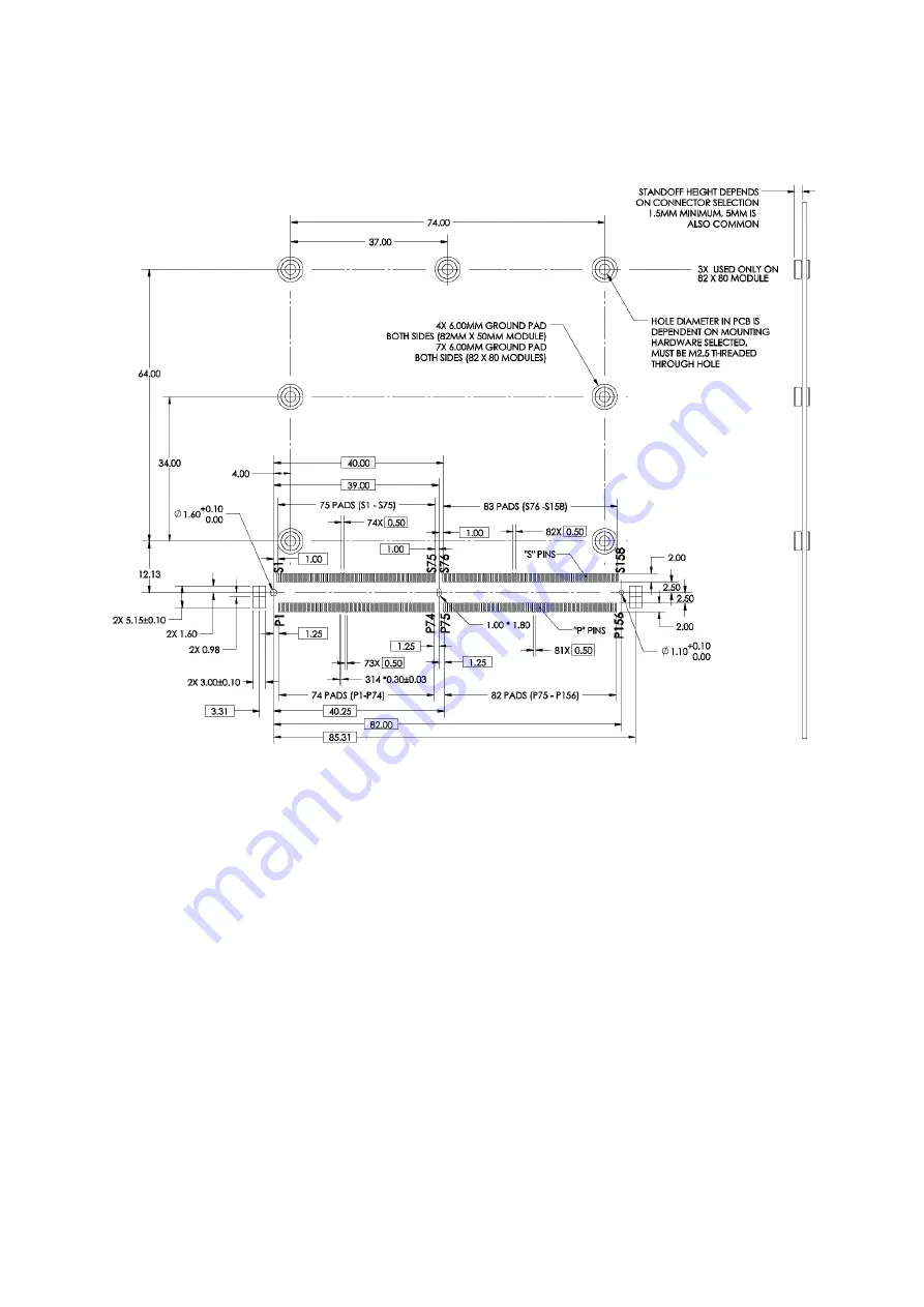
4.5 Carrier Board Connector PCB Footprint
Figure 48: Carrier Board Connector PCB Footprint
Note:
The hole diameter for the 4 holes (82mm x 50mm Module) or 7 holes
(82mm x 80mm Module) depends on the spacer hardware selection. See
the section below for more information on this.
Содержание SMARC T335 Series
Страница 2: ...SMARC T335x Carrier Board Hardware Design Guide Document Revision 1 2 ...
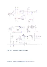
Страница 118: ...SMARC T335x Carrier Board Hardware Design Guide Document Revision 1 2 Figure 44 Power Supply Reference Schematic ...
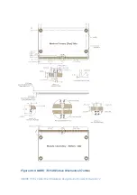
Страница 124: ...SMARC T335x Carrier Board Hardware Design Guide Document Revision 1 2 Figure 46 SMARC T335X Module Mechanical Outline ...


