SMARC T335x Carrier Board Hardware Design Guide, Document Revision 1.2
2.9 SPI Interface
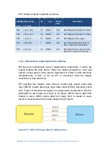
The Serial Peripheral Interface (SPI) is a 4-pin interface that provides a
potentially lower-cost alternative for system devices such as EEPROM and
flash components.
SMARC
standard features two optional SPI ports. Each port defines two chip
select signals that can connect up to two SPI devices.
SMARC T335X
features two SPI interfaces. The
SPI0_CS0#
is taken to
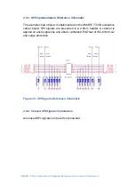
connect a 4MB serial flash on module. If users would like to use SPI0 port, use
SPI0_CS1
as chip select signal instead. The
SPI0_CS0#
signal in evaluation
carrier of
SMARC T335X
can be used when developers use
SMARC
modules
from other vendors.
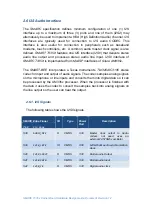
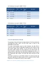
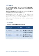
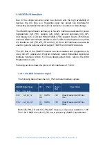
2.9.1. SPI Signals
The following table shows the
SPI0
interface signals.
SMARC Edge Finger
I/O
Type
Power
Rail
Description
Pin#
Pin
Name
P31
SPI0_CS1#
O
CMOS
3.3V
SPI0 Master Chip Select 1 output
P43
SPI0_CS0#
O
CMOS
3.3V
SPI0 Master Chip Select 0 output,
reserve for onboard NOR flash
P44
SPI0_CK
O
CMOS
3.3V
SPI0 Master Clock output
P45
SPI0_DIN
I
CMOS
3.3V
SPI0 Master Data input (input to
CPU, output from SPI device)
P46
SDIO_DO
O
CMOS
3.3V
SPI0 Master Data output (output
from CPU, input to SPI device)
Содержание SMARC T335 Series
Страница 2: ...SMARC T335x Carrier Board Hardware Design Guide Document Revision 1 2 ...
Страница 118: ...SMARC T335x Carrier Board Hardware Design Guide Document Revision 1 2 Figure 44 Power Supply Reference Schematic ...
Страница 124: ...SMARC T335x Carrier Board Hardware Design Guide Document Revision 1 2 Figure 46 SMARC T335X Module Mechanical Outline ...

