SMARC T335x Carrier Board Hardware Design Guide, Document Revision 1.2
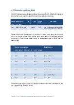
The boot mode selection of
SMARC T335X
is listed in the following table.
Carrier Connection
BOOT_SEL2# BOOT_SEL1# BOOT_SEL0#
Boot Source
0
GND
GND
Float
Carrier SD Card
1
Float
Float
GND
Module eMMC Flash
2
GND
Float
Float
Carrier SPI
Note:
The BOOT_SELx#
configuration will be decoded to
SYSBOOT
on
module and recognized by
AM335X
. The ROM code of
AM335X
will know
where to load the 2
nd
stage bootloader (SPL) based on the
SYSBOOT
configuration during the 1
st
stage initiation.
If the boot mode is selected to carrier SD card and SD card is not
presented, AM335x will look for SPI0 as next boot device. Please see
“AM335x ARM Cortex-A8 Microprocessors (MPUs), rev F”
from Texas
Instrument for more details.
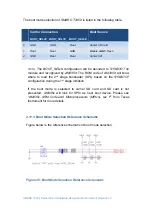
2.11.1. Boot Mode Selection Reference Schematic
Figure below is the reference schematic of boot mode selection.
Figure 35: Boot Mode Selection Reference Schematic
Содержание SMARC T335 Series
Страница 2: ...SMARC T335x Carrier Board Hardware Design Guide Document Revision 1 2 ...
Страница 118: ...SMARC T335x Carrier Board Hardware Design Guide Document Revision 1 2 Figure 44 Power Supply Reference Schematic ...
Страница 124: ...SMARC T335x Carrier Board Hardware Design Guide Document Revision 1 2 Figure 46 SMARC T335X Module Mechanical Outline ...

