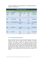
SMARC T335x Carrier Board Hardware Design Guide, Document Revision 1.2
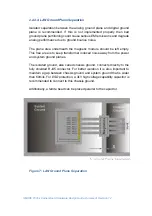
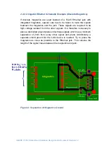
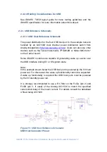
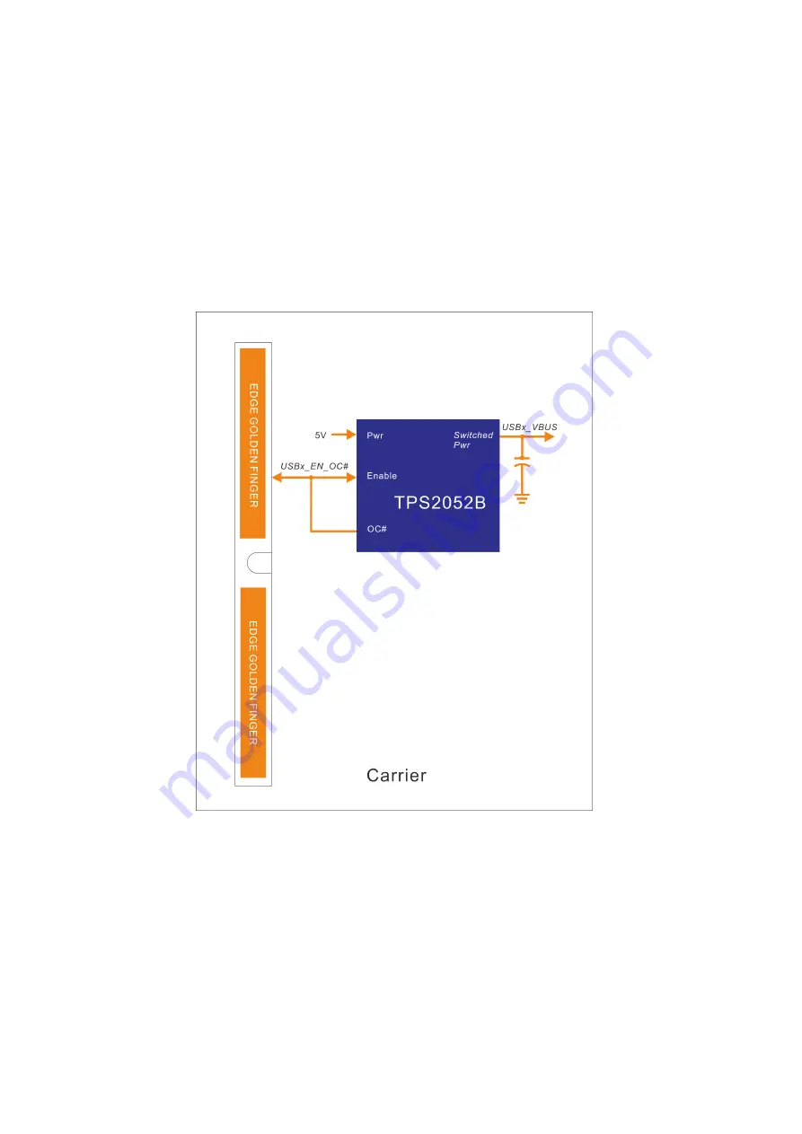
Carrier USB power switches have active-high power enables and
active low open drain
OC#
outputs (as the TI and Micrel devices
referenced do). The USB power switch Enable and
OC#
pins for a
given USB channel are tied together on the Carrier. The USB power
switch enable pin must function with a low input current. The TI and
Micrel devices referenced above require 1 microampere or less, at a
3.3V enable voltage level.
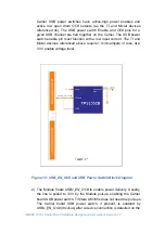
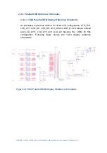
Figure 12: USB_EN_OC# and USB Power Switch Block Diagram
2) The Module floats
USBx_EN_OC#
to enable power delivery. Usually,
the line is pulled to 3.3V by the Module pull-up, enabling the Carrier
board USB power switch. Ti Sitara AM335x does not need the pull-ups.
The Carrier board USB power switch, if present, is enabled by
USBx_EN_OC# (drvvbus) after a device connection is detected on the
Содержание SMARC T335 Series
Страница 2: ...SMARC T335x Carrier Board Hardware Design Guide Document Revision 1 2 ...
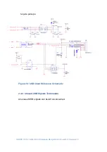
Страница 118: ...SMARC T335x Carrier Board Hardware Design Guide Document Revision 1 2 Figure 44 Power Supply Reference Schematic ...
Страница 124: ...SMARC T335x Carrier Board Hardware Design Guide Document Revision 1 2 Figure 46 SMARC T335X Module Mechanical Outline ...


