SMARC T335x Carrier Board Hardware Design Guide, Document Revision 1.2
2.2.2. LAN Implementation Guidelines
The most critical component in the
LAN
interface is the isolation magnetics
connected directly to the
MDI
differential pair signals of the
SMARC
module.
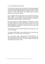
It should be carefully qualified for Return Loss, Insertion Loss, Open Circuit
Inductance, Common Mode Rejection and Crosstalk Isolation to pass the
IEEE conformance tests and
EMI
tests.
Even if a
SMARC
module complies with the basic specifications set forth for
IEEE certification, it's still possible that the overall system could fail IEEE
testing because of a poor quality or unsuitable external isolation magnetics
module and/or improper PCB layout of the carrier board.
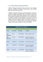
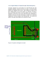
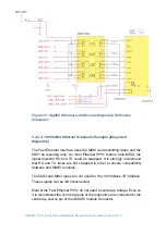
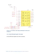
Ethernet connectors with integrated magnetics are preferable. If a design
with external magnetics is chosen, additional care has to be taken to route
the signals between the magnetics and Ethernet connector. If only Fast
Ethernet (100Mbit/s) is required, some design cost may be saved by using
only
10/100Base-TX
magnetics.
The Ethernet
MDI
signals are analogue differential pair signals which need
to be routed carefully.
Try to keep the
MDI
signals as short as possible and keep them away from
digital signals. Try to avoid any stubs on these signals.
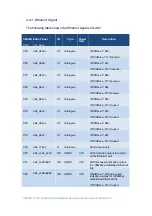
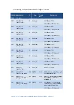
The LED output signals
GBE_LINK_ACT#
,
GBE_LINK100#
and
GBE_LINK1000#
can be connected directly to the LED of the Ethernet jack
with suitable serial resistors. There is no need for additional buffering if the
current draw does not exceed 10mA.
Содержание SMARC T335 Series
Страница 2: ...SMARC T335x Carrier Board Hardware Design Guide Document Revision 1 2 ...
Страница 118: ...SMARC T335x Carrier Board Hardware Design Guide Document Revision 1 2 Figure 44 Power Supply Reference Schematic ...
Страница 124: ...SMARC T335x Carrier Board Hardware Design Guide Document Revision 1 2 Figure 46 SMARC T335X Module Mechanical Outline ...

