SoM-A5D36 User Manual
Revision 1.30 © 2015
- 21 -
2.5
Power Connections
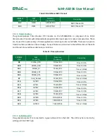
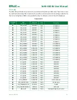
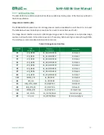
The SoM-A5D36 requires a 3.3V supply for the Bus and I/O voltages. The 1.2V core voltage is regulated on
module from the 3.3V. Unlike some other modules no other supply voltage other than 3.3V is required.
Table 24: Power Connections
SODIMM
Pin#
SoM
Pin Name
Processor
Pin Name(s)
Description
3,4,43,44,135,
136,197,198
3.3VCC
3.3VCC
3.3 Volt SoM Supply Voltage
1,2,20,21,41,42,
91,92,137,138,
155,156,199,200
GND
GND
Digital Ground
53
Analog_GND
ADC_GND
Analog Ground
56
VSTBY
Vstandby_3.3 Voltage standby, this is the backup voltage
provided to the SoM’s RTC. If RTC readings are not
important for the application, this can be attached
to the 3.3V rail.
55
AV_REF
NC
Analog power/reference. This voltage provides
power to the internal analog circuitry of the
processor. It can be typically connected to 3.3V. LC
filtering for this power signal is provided on-
module.
2.6
Boot Options
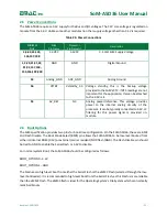
The SoM specification provides two pins for boot-time configuration. On the SoM-A5D36, these are BMS
and Flash Disable. The Boot Mode Select (BMS) pin allows the SoM-A5D36 to be low-level booted from
either its internal ROM (3.3V) or external (carrier resident) NOR flash (GND). The Flash Disable pin should
be tied to GND to enable the Serial Flash or 3.3V to disable.
For normal system Boot, the SoM-A5D36 should be configured as follows:
BOOT_OPTION0
–
3.3V
BOOT_OPTION1
–
GND
The Module can high-level boot from either the Serial Flash or the eMMC Flash (selected through the low-
level bootloader). It is recommended to high-level boot from the Serial Flash, as this Flash is more reliable
than the eMMC Flash. The eMMC flash is ideal for the Operating System’s File System which can normally
mark bad blocks.


