SoM-A5D36 User Manual
Revision 1.30 © 2015
- 12 -
2.4.6
SPI
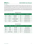
The ATSAMA5D36 processor provides two SPI (Serial Peripheral Interface) channels, SPI0 and SPI1, for
communicating with peripheral devices. The SPI0 bus is connected internally to the serial flash, which uses
SPI0_NPCS0 (SPI0_NPCS0 is not brought out to the card fingers). Table 8 below lists the lines for SPI
channel 0. Table 9 below lists the lines for the SPI channel 1. These pins have shared functions and can
be accessed through the GPIO header on the SoM-200 carrier board. Note SPI Chip Selects (CS) for both
Linux & WinCE do not require a specific SPI_CS and as such can use any GPIO allowing additional chip
selects if a custom carrier is used.
Table 8: SPI Channel 0
SODIMM
Pin#
SoM
Pin Name
Processor
Pin Name(s)
Port Line
Description
22
SPI_MI
SPI0_MISO
PD10
SPI0 serial data in
23
SPI_MO
SPI0_MOSI
PD11
SPI0 serial data out
24
SPI_SCK
SPI0_SPCK
PD12
SPI0 serial clock out
25
SPI_CS0
SPI0_NCS1/CANRX0
PD14
SPI0 slave select line 0
26
SPI_CS1
SPI0_NCS2/CANTX0
PD15
SPI0 slave select line 1
27
SPI_CS2
SPI0_NCS3
PD16
SPI0 slave select line 2
28
SPI_CS3
SPI0_NCS4/PWMFI2
PC28
SPI0 slave select line 3
Table 9: SPI Channel 1
SODIMM
Pin#
SoM
Pin Name
Processor
Pin Name(s)
Port Line
Description
126
GPIO12
SPI1_MISO
PC22
SPI1 serial data in
127
GPIO13
SPI1_MOSI
PC23
SPI1 serial data out
128
GPIO14
SPI1_SPCK
PC24
SPI1 serial clock out
134
GPIO15
SPI1_NCS0
PC25
SPI1 slave select line 0
40
USB_OTG_ID
SPI1_NCS1
PC26
SPI1 slave select line 1
10
USB_OTG_VBUS
SPI1_NCS2
PC27
SPI1 slave select line 2


