SoM-A5D36 User Manual
Revision 1.30 © 2015
- 17 -
2.4.12
Interrupts
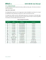
The SoM specification defines 3 interrupt lines however, any GPIO on the ATSAMA5D36 processor may
be programmed for interrupts.
Table 18: Interrupt Lines
SODIMM
Pin#
SoM
Pin Name
Processor
Pin Name(s)
Description
129
IRQA
FIQ/PC31
Fast Interrupt Request
130
IRQB
IRQ/PE31
General Interrupt Request
131
IRQC
PE29
General Interrupt Request
2.4.13
ADC
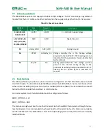
The SoM-200 Pin Specification allocates SoM pins that can be utilized as Touchscreen or ADC inputs. Also,
if a touchscreen is not used, the lines that would normally be used in this capacity can also be used as ADC
inputs. The ATSAMA5D36 features a 12-channel, 12-bit ADC that can be used in single or dual ended
configuration. Ten of these channels are available through the edge connector. The first four lines are
used for a typical resistive 4-wire touchscreen. The ATSAMA5D36 does support 5 wire touchscreens. In
addition to the 8 ADC pins allocated by the SoM specification there are an additional 2 ADC channels
available through alternative pin functions. The analog reference is enabled by default, but it can be
turned off if you are not using the touchscreen or ADC inputs by changing PB25 to an output and driving
it low. The SoM-A5D36 provides a filtered onboard 3.3 Volt reference for the ADC.
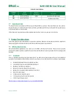
Table 19: Analog to Digital Converters
SODIMM
Pin#
SoM
Pin Name
Processor
Pin Name(s)
Port Line
Description
45
X+/Xr/ADC0
AD0
PD20
X+ or ADC0
46
X-/Xl/ADC1
AD1
PD21
X- or ADC1
47
Y+/Yu/ADC2
AD2
PD22
Y+ or ADC2
48
Y-/Yd/ADC3
AD3
PD23
Y- or ADC3
49
SX+/ADC4
AD4
PD24
SX+ or ADC4
50
SX-/ADC5
AD5
PD25
SX- or ADC5
51
SY+/ADC6
AD6
PD26
SY+ or ADC6
52
SY-/ADC7
AD7
PD27
SY- or ADC7


