SoM-A5D36 User Manual
Revision 1.30 © 2015
- 13 -
2.4.7
MCI Multimedia Card
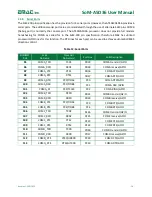
The SoM-A5D36 provides two 4-bit MMC/SD card interfaces, MCI1 and MCI2. The SoM-200 specification
provides for three associated but optional SD/MMC control lines. Since these lines are optional and will
not always be used they are not part of the SD/MMC group but are part of the GPIO group. SoM pin#s
122, 123, and 124 can be used as SD_LED, SD_Power, and SD_protect, respectively.
MCI1 is allocated to the SoM Pin Specification in the SD/MMC section as the default SD port. When
designing a custom carrier, MCI1 should be used rather than MCI2 if you want to maintain compatibility
with present and future SoMs. The SoM-200GS/250G
S Carrier boards’ memory sockets ma
ke use of MCI1.
The MCI2 interface should only be used if you are not concerned about compatibility with existing and
future SoMs. MCI2 is accessed through the SoM-
A5D36’s GPIO section.
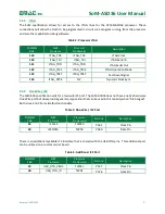
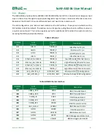
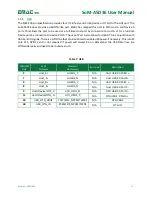
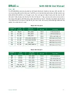
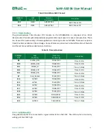
Table 10: MMC/SD Card Interface
SODIMM
Pin#
SoM
Pin Name
Processor
Pin Name(s)
Port Line
Description
31
SDCLK
MCI1_CLK
PB24
MCI Clock
32
CMD
MCI1_CDA
PB19
MCIB Command
33
DAT0
MCI1_DA0
PB20
MCIB D0
34
DAT1
MCI1_DA1
PB21
MCIB D1
35
DAT2
MCI1_DA2
PB22
MCIB D2
36
DAT3
MCI1_DA3
PB23
MCIB D3
37
Card_Detect
PC5/TCLK4
PC5
Card Detect
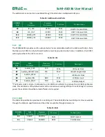
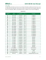
An additional MMC/SD interface is available through shared GPIO lines. All the lines for the second
MMC/SD port are brought out to a header on the SoM-200 carrier.
Table 11: Additional MMC/SD Card Interface
SODIMM
Pin#
SoM
Pin Name
Processor
Pin Name(s)
Port Line
Description
125
GPIO11
MCI2_CK/PCK2
PC15
MCI Clock
120
GPIO6
MCI2_CDA
PC10
MCIC Command
121
GPIO7
MCI2_DA0
PC11
MCIC D0
122
GPIO8
MCI2_DA1/TIOA1
PC12
MCIC D1
123
GPIO9
MCI2_DA2/TIOB1
PC13
MCIC D2
124
GPIO10
MCI2_DA3/TCLK1
PC14
MCIC D3


