SoM-A5D36 User Manual
Revision 1.30 © 2015
- 20 -
2.4.17
Additional Interfaces
The SoM-A5D36 has additional optional interfaces available by trading some of the features outlined in
the SoM specification.
Image Sensor Interface (ISI):
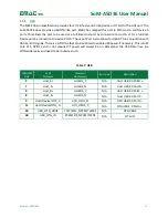
The ATSAMA5D36 Processor has a 12-bit Image Sensor Interface available for use if the LCD is not used.
The table below shows the SoM pin connections for a custom carrier that uses the ISI.
The Image Sensor Interface connects a CMOS-type image sensor to the processor and provides image
capture in various formats. It does data conversion, if necessary, before storing in memory through DMA.
The interface can accommodate both 8 and 12-bit sensors.
Table 23: Image Sensor Interface
SODIMM
Pin#
SoM
Pin Name
Processor
Pin Name(s)
Description
73
LCD_RED0
ISI_D0/LCDDAT16
ISI Data 0
74
LCD_RED1
ISI_D1/LCDDAT17
ISI Data 1
75
LCD_RED2
ISI_D2/LCDDAT18
ISI Data 2
76
LCD_RED3
ISI_D3/LCDDAT19
ISI Data 3
77
LCD_RED4
ISI_D4/LCDDAT20
ISI Data 4
78
LCD_RED5
ISI_D5/LCDDAT21
ISI Data 5
79
LCD_RED6
ISI_D6/LCDDAT22
ISI Data 6
80
LCD_RED7
ISI_D7/LCDDAT23
ISI Data 7
112
COMD_CTS
ISI_D8/PC29
ISI Data 8
28
SPI_CS3
ISI_D9/PC28
ISI Data 9
10
USB_OTG_VBUS
ISI_D10/PC27
ISI Data 10
40
USB_OTG_ID
ISI_D11/PC26
ISI Data 11
113
COMD_RTS
ISI_PCK/PC30
ISI Pixel Clock
30
I2C_DATA
ISI_VSYNC/PA30
ISI Vertical Sync
29
I2C_CLK
ISI_HSYNC/PA31
ISI Horizontal Sync


