SoM-A5D36 User Manual
Revision 1.30 © 2015
- 15 -
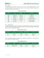
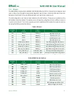
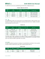
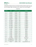
The additional 2 serial ports are available through the alternative multiplexed SoM pins.
Table 13: Additional Serial Ports
SODIMM
Pin#
SoM
Pin Name
Processor
Pin Name(s)
Port Line
Pin Description
29
I2C_CLK
UTXD1
PA31
UART 1 Transmit Data
30
I2C_DAT
URXD1
PA30
UART 1 Receive Data
113
COMD_RTS
UTXD0
PC30
UART 0 Transmit Data
112
COMD_CTS
URXD0
PC29
UART 0 Receive Data
2.4.9
I2S
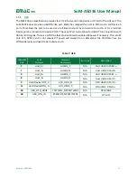
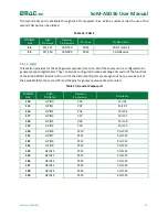
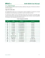
The ATSAMA5D36 provides an I2S audio port which is accommodated within the SoM specification. Note
that there is no CODEC on the SoM and therefore must be provided on the Carrier. In addition, the CODEC
will require either SPI or I2C for control.
Table 14: I2S
SODIMM
Pin#
SoM
Pin Name
Processor
Pin Name(s)
Port Line
Description
86
AudioA_SCLK
TK0
PC16
I2S Serial Clock
87
AudioA_LRCLK/Frame
TF0
PC17
I2S Left / Right Clock
88
AudioA_MCLK
*
*
I2S Master Clock
89
AudioA_DIN
RD0
PC21
I2S Data Input
90
AudioA_DOUT
TD0
PC18
I2S Data Output
*The Master clock is driven On-Module by a 12.288 MHz oscillator to produce the 12.288 MHz Master
clock. This oscillator is off by default and must be turned on via setting GPIO port line PC19 High. To reduce
power the oscillator should be turned off when not required.
2.4.10
CAN
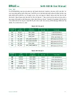
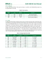
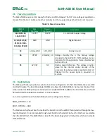
The SoM-200 specification provides for one CAN port. The SoM-A5D36 has two CAN ports. One is available
through the SoM pin specification and the other is available through shared pins.
Table 15: CAN
SODIMM
Pin#
SoM
Pin Name
Processor
Pin Name(s)
Port Line
Pin Description
93
CANTX
CANTX1
PB15
CAN Transmit
94
CANRX
CANRX1
PB14
CAN Receive


