20
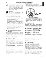
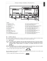
Connect the equipment water supply pipes to the
water system, interposing a cock, filter and pressure
gauge.
Figure 8 Water connection
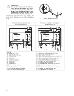
IMPORTANT!
Connect the wash zone to the hot water
inlet; connect the prewash zone to the
cold water inlet and connect the rinse
zone to the hot water inlet if the con-
densing unit (CU) is not present, and to
the cold water inlet if the CU is present.
!
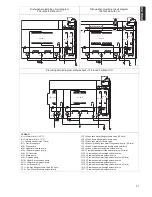
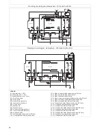
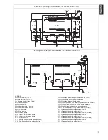
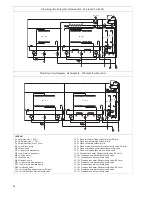
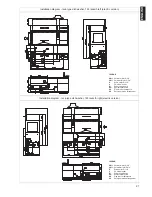
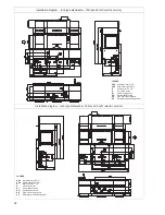
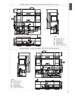
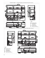
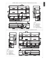
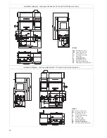
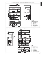
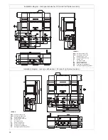
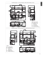
Dishwasher plumbing circuit diagram
140 racks/h without CU
Dishwasher plumbing circuit diagram
140 racks/h with CU
LEGEND
A = Hot water inlet (~ 50°C)
B = Cold water inlet (~ 15°C)
C = Variable shutter (max 7 l/min)
M1 = Duo-Rinse pump
M2 = Rinse pump
M4 = Upper arms wash pump
M5 = Lower arms wash pump
M6 = CU fan motor
M7 = Wash pump
M8 = Prewash pump
M10 = Upper arms prewash pump
M11 = Lower arms prewash pump
ABV = Air Break Valve
YV1 = Air-Gap filling solenoid valve (20 l/min)
YV2 = Duo-Rinse tank drain solenoid valve
YV3 = Wash tank water filling solenoid valve (20 l/min)
YV4 = Wash pump discharge solenoid valve
YV5 = Wash tank drain solenoid valve
YV6 = Wash or prewash tank water filling solenoid valve (20 l/min)
YV7 = Wash or prewash pump discharge solenoid valve
YV8 = Wash or prewash tank drain solenoid valve
YV9 = Prewash tank water filling solenoid valve (20 l/min)
YV10 = Prewash pump discharge solenoid valve
YV11 = Prewash tank drain solenoid valve
YV12 = Prewash tank water filling solenoid valve (20 l/min)
YV13 = Prewash pump discharge solenoid valve
YV14 = Prewash tank drain solenoid valve
YV15 = Prewash tank water filling solenoid valve (20 l/min)
YV16 = Prewash pump discharge solenoid valve
YV17 = Prewash tank drain solenoid valve
M7
YV7
YV8
YV6
55-65°C
YV1
M2
M1
YV2
ABV
C
A
60-70°C
80-90°C
M7
YV7
YV8
YV6
55-65°C
M6
YV1
M2
ABV
M1
YV2
60-70°C
180 m
3
/h
A
B
C
ABV
80-90°C


