EPV 701 User Manual
Doc. No
:
RGB-RD-UM-V618E012
5
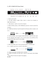
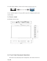
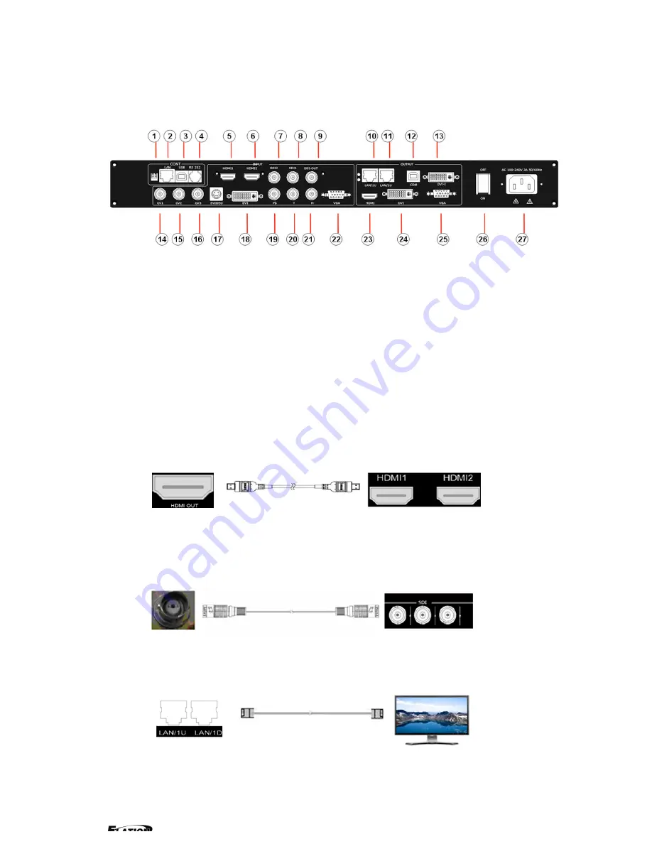
3.1 EPV IMAGE VSC Back Panel
1
、
Dial the code switch
;
2
、
10/100M interface (copper RJ45). Used to connect the computer by
568B-568A twist-pair
3
、
USB interface
,
Used to connect the computer
4
、
RS232 interface (RJ11) for EPV IMAGE VSC processor. Used to connect the
computer;
5-6
、
HDMI input interface
。
Input the signal from HD player, DVD, computer, and
so on.
7-8
、
SDI Input BNC, used to support SD/HD SDI input
。
Input the video signal
from the HD player, HD projector. It can connect to the 7 or 8 interface on the
next EPV IMAGE VSC,using the 75ohm BNC.
9
、
SDI loop out BNC, used to loop input SDI signal to next SDI player.
10-11
、
Gigabit copper port, connect to LED screen.
12
、
Gigabit Transmitter card USB control interface;
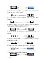
13
、
Gigabit Transmitter card DVI input
,
connect to DVI output of EPV IMAGE
VSC;
(
This Connection does not support hot-plugging
)
Содержание EPV IMAGE VSC
Страница 1: ...EPV IMAGE VSC VIDEO PROCESSOR USER MANUAL ...
Страница 22: ...EPV 701 User Manual Doc No RGB RD UM V618E012 17 ...


