background image

35

2

3

4

1

Operator’s Manual City Ranger 3070 

Operator’s Manual City Ranger 3070

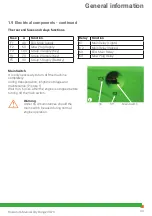
Floor nozzles

Cabin heating

Keypad 2

1.11  Heating and air condition

Cabin heating

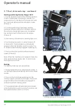
To switch on cabin heating, press the cabin heat 

increase button and turn on the cabin fan

(Section 1.6, Keypad 2).

The cabin temperature can be adjusted in 10 

steps and the fan in 3 steps for optimal comfort. 

The cabin heat level is shown in the display and 

the cabin fan speed is indicated by the diodes 

above the button. (Picture 1)

Air conditioning

To cool down the cabin, switch on the air 

conditioning and adjust the cabin fan speed on 

the keypad, located on the armrest.

NB: The air conditioning unit and the cabin filter 

must be checked/cleaned once a year

Cabin ventilation

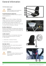
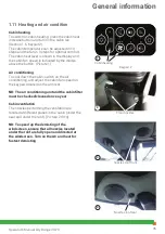
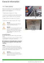
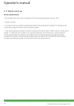
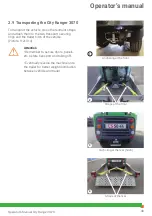
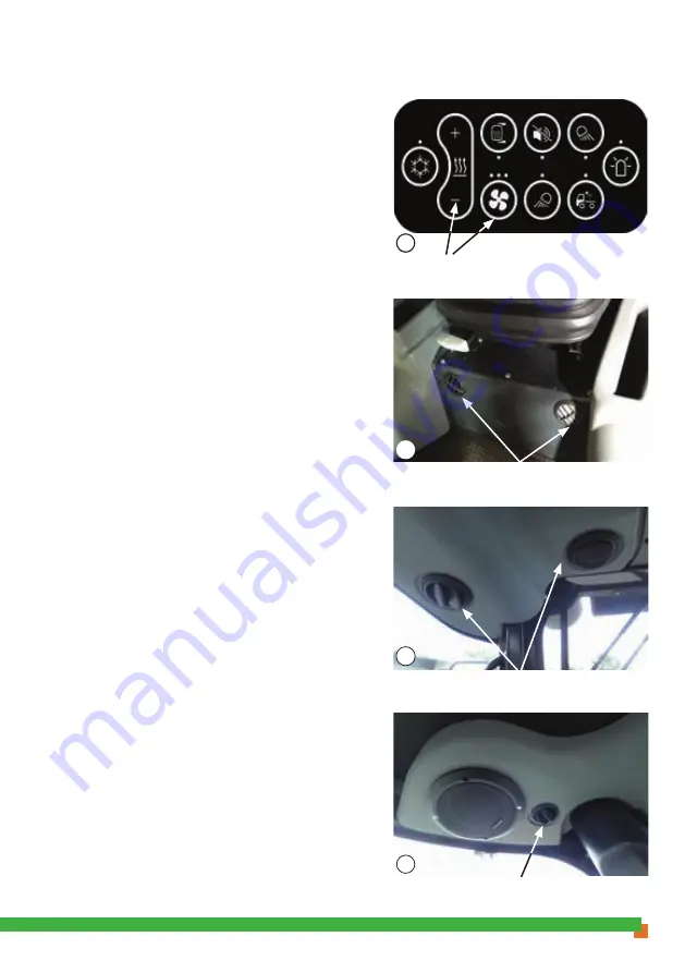
The nozzles performing the ventilation are 

located at different places in the cabin (under the 

seat and under the roof). (Picture 2+3+4)

NB: To speed up the demisting of the

windscreen, ensure that all nozzles located

under the roof are fully open and directed at

the windscreen. Turn on the AC and heat for 

fastest demisting

nozzles roof front

Nozzles roof rear

General information

Содержание City Ranger 3070

Страница 1: ...Operator s manual Basic machine City Ranger 3070 ...

Страница 2: ...ompetent operator Do not lend it to anyone who has not been thoroughly trained and who has not read this manual carefully The operator s manual should be considered a permanent part of the machine and must remain with the machine if sold Warnings Some items in this operator s manual are marked with this warning symbol see figure 1 The warning indicates areas where extra care has to be taken to avo...

Страница 3: ...0 2 1 Transport mode 40 2 2 Work mode 40 2 3 Manuel mode 41 2 4 Daily checks before start up 42 2 5 Cleaning and checking after each use 43 2 6 Fuel filling 44 2 7 Start drive and stop 45 2 8 Engine warm up 48 2 9 Transporting the City Ranger 3070 49 Service and maintenance 51 3 1 City Ranger 3070 service and maintenance chart 51 3 2 Engine oil 53 3 3 Hydraulic oil 55 3 4 Coolant 57 3 5 Brake flui...

Страница 4: ...Introduction ...

Страница 5: ...urther it provides you with a very fast and easy quick change system which save you a lot of time The City Ranger 3070 can be equipped with a full range of tailor made quality attachments fully integrated and designed to work with the machine ensuring high performance in every task Examples of tasks Green care Snow removal Suction sweeping Comfort The City Ranger 3070 is an utility machine with a ...

Страница 6: ...General information ...

Страница 7: ...tor to assure safe operation Emptying the hopper on an incline Manoeuvring the machine with raised hopper Abrupt steering Manoeuvring with speed on a slope or with weight on A frame B frame Manoeuvring with high speed in sharp turns Manoeuvring the machine on an irregular ground Low tyre pressure Avoid standing close to the machine while it is in use Make sure that no person is near the machine wh...

Страница 8: ...only Other hazards There may be other circumstances and situations than those mentioned above where it may be dangerous to use the City Ranger 3070 Take care while handling potentially dangerous products Do not smoke when filling up Do not spill diesel on the engine the mechanical parts or the vehicle body The brake fluid is very harmful and very corrosive Avoid contact with the skin and eyes In c...

Страница 9: ...connected to conserve battery power Maintenance Egholm is by no means responsible for damages or accidents caused by misuse or by a lack of maintenance of the vehicle When non original spare parts are used or attachments or other components are used which are not approved by Egholm the guarantee will not apply Only work in the engine compartment when engine is turned off and cooled Keep a safe dis...

Страница 10: ...an operator s manual for each attachment Operation with these attachments must follow the instructions outlined in the relevant operator s manual Do not operate the City Ranger 3070 with the attachment unless all instructions have been followed General information ...

Страница 11: ...on of implements accessories or other equipment not manufactured by Egholm automatically results in the cancellation of type approval CE approval any other approval as well as any warranty on machine and attachments Unless otherwise agreed in writing between the operator customer and Egholm Egholm is the data originator data originator of all data generated by the machine and attachments during us...

Страница 12: ...ht Kerb weight without driver incl fuel Gross vehicle weight rating Payload Maximum vertical load on coupling point Permitted axle load front Permitted axle load rear 1 710 kg 3 000 kg 1 290 kg 100 kg 2 000 kg 2 000 kg Operating temperature Temperature range For operations From 18 C to 40 C From 25 C to 18 C Tyres Standard All year winter M S Tyre pressure Wide tyre Extra comfort Tyre pressure Gra...

Страница 13: ...orque Engine speed at maximum torque Emissions Fuel Fuel tank capacity Diesel Perkins 404F E22TA 4 2 200 cm3 50 kW 67 1 hp 2 800 rpm 208 Nm 1 800 rpm EU Stage IIIB U S EPA Tier 4 Final 50 l Lubricating system std conditions Total engine lub system capacity dry engine 10 6 l synthetic Engine oil viscosity depends on the working temperature Engine oil specifications API CJ 4 standard SAE10W 30 Cooli...

Страница 14: ...lic system capacity all system Approx 60 l synthetic Standard type Texaco Rando HDE68 Brakes Service brakes Hydraulic drum brakes on front wheels Parking brakes Spring loaded brakes on rear wheels Emergency Hydrostatic braking Driving Speed forward Max 40 km h 25 mph Speed rearward Max 10 km h 6 mph Air conditioning Gas R 134a 425 g Oil SP10 for high low temperatures the data should be reviewed Ge...

Страница 15: ...ling Object Protective Structure FOPS The City Ranger 3070 and its attachments do not operate when falling objects are a risk Roll Over Protective Structure ROPS Tested according to Regulation EU 1322 2014 annex X and fulfills OECD Code 7 Contact with hazardous substances The air intake contains a filter to protect the driver against dust inhalation Cabin classification according to EN 15695 1 is ...

Страница 16: ...e way use the entrance step to leave the cabin Attention There is a similar door on the right side This door is operated in the same way as the left door and can be used as an emergency exit Attention Always lock the machine when leaving Never leave keys in ignition lock Attention Keep the cabin free of loose items that may interfere with safe operation of the machine Always store items in the sto...

Страница 17: ...ort and usability The controls are built into the right armrest the steering column and into floor pedals In this chapter the controls and their functionalities are described Arm rest controls Armrest 1 Display 2 Right joystick 3 Keypad 1 4 Direction switch Forward Parking Reverse See 1 6 Controls page 17 5 Keypad 2 6 Left joystick General information ...

Страница 18: ... column Picture 1 1 Multifunction switch 2 Light switch see Section 1 8 3 Steering wheel 4 Hazard light see Section 1 8 5 Ignition key Floor pedals Picture 2 see Section 1 8 1 Drive pedal 2 Inch brake pedal Steering column controls 2 Inch brake pedal 1 Drive pedal General information ...

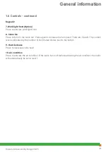
Страница 19: ...ion switch is pushed forward the machine will drive forward the center position is parking and if pulled backwards the machine will drive backwards When in parking position the parking brake automatically engages When in forward or reverse the parking automatically disengages Picture 2 Multifunction switch 1 Horn 2 Washer fluid 3 Direction indicator Move the lever up to indicate right turn Move th...

Страница 20: ...ransfer The operator can adjust the pressure of which the selected attachment is pressed against the road ground by using the weight transfer functionality This function is only applicable in work mode When active the diode next to the button is illuminated Weight transfer will automatically disable if right joystick is activated in either forward or reverse direction or if operation mode is chang...

Страница 21: ... function is only applicable in work mode When active the diode next to the button is illuminated Floating position will automatically disable if right joystick is activated in either forward or reverse direction or if operation mode is changed to transport or manual mode 8 Speed Limitation Press to select speed level from 1 to 3 The number of illuminated diodes indicates which level is active 3rd...

Страница 22: ...the display 2 Mirror heat Option Press to turn on the mirror heat 3 Reverse alarm off Option Press to disable the reverse alarm Only disable when the noise is unacceptable and it is safe to disable 4 Work light rear Option Press to turn work light in the rear of the machine 5 Beacon light Option Press to activate beacon light 6 Loading light Option Press to activate loading light General informati...

Страница 23: ...fan Press again to increase the fan speed There are 3 levels The current level is indicated by the number of illuminated diodes next to the button 9 Heat decrease Press to decrease cabin heat 10 Air condition Press to activate the air condition If the cabin fan is off before activating the air condition the cabin will automatically be set to level 1 General information ...

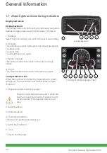
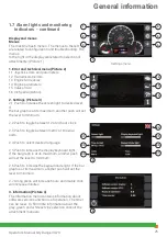
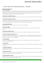
Страница 24: ...urn one level This button returns the screen to the one previously shown 4 Home This button returns the screen to the startup screen Transportation screen When the machine is started the transportation screen will appear The transport mode display screen shows Picture 2 1 Engine coolant temperature gauge Engine coolant temperature is 82 C when the needle is in vertical position Operation is not re...

Страница 25: ...d level If the bar graph is at its maximum another push will set the level to minimum 2 2 Push to toggle between 12 or 24 hour clock 2 3 Push to toggle between metric or imperial units 2 4 Push to select desired language 2 5 Push to increase the display keyboard light If the bar graph is at its maximum another push will set the level to minimum 2 6 Push to increase the keypad diode light If the ba...

Страница 26: ...en the liquid is under pressure There is a risk of accidents 1 Left direction indication Appears when the indicator arm points to the left or if the hazard switch is on 2 Hazard light Flashes when the hazard button is on along with the right and left indication arrows 1 and 3 3 Right direction Appears when the indicator arm points to the right or if the hazard switch is on 4 Amber warning light Th...

Страница 27: ...ngine is preheating The engine will not start if the symbol is shown in the display 10 Engine coolant level alarm Appears if the engine coolant level is too low Stop to investigate for leakages and refill engine coolant 11 Engine coolant temperature alarm Appears if the engine coolant exceeds 112 C PTO front and rear are deactivated to protect the engine PTO front and rear resume when the temperat...

Страница 28: ... 2 Inch brake pedal Pressing the pedal will engage engine braking If pressed further both engine brake and drum brakes are applied to achieve maximum braking performance Storage box The cabin AC system is connected to the storage box so when the cabin AC is activated cooling inside the box is possible If the cabin heating is active the nozzle inside the storage box can be closed Picture 3 Attentio...

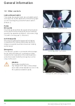
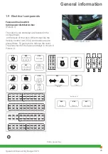
Страница 29: ...tor s Manual City Ranger 3070 1 9 Electrical components Fuses and main switch Cabin power distribution box Picture 1 The cabin fuses and relays are located in the compartment on the back of the cabin Other things like the Vehicle Control Unit VCU and diodes are also placed there To gain access remove the cover The placement of the fuses and relays is shown in Picture 2 Cabin back cover Cabin power...

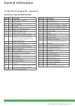
Страница 30: ...28 20 Cabin fan F29 15 Low Beam F30 15 Work Light Left F31 15 Work Light Right F32 10 Wiper F33 1 Sensor Tachometer Engine inlet air filter Trailer plug switch F34 5 ECU Cranking Signal Fuse A Function F35 5 Key Switch F36 5 Fuel Pump Coil F37 25 VCU Output Supply 1 Valves F38 25 VCU Output Supply 2 Valves F39 30 VCU Output Supply 3 Valves F40 20 Mirror Heat F41 20 Seat F42 1 Seat Switch F43 7 5 R...

Страница 31: ...eam K14 Stop Light Trailer K15 Fuel Pump K16 VCU Display Supply K17 Wiper Supply Relay K18 A C Compressor K19 Actuator Forward K20 Actuator Reverse K21 Actuator Front Rear K22 Digital Output Rear K23 Wiper Timer Relay K24 Flasher Relay K25 Fan Speed low K26 Fan Speed middle K27 Fan Speed high DIODES Diode Function V1 VCU Display Supply Activation Hazard Light V2 VCU Display Supply Activation Key G...

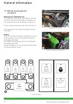
Страница 32: ...cture 2 The placement of the fuses and relays is shown in Picture 3 Battery When connecting or replacing the battery be sure that the power cords are connected correctly to the battery terminals Be careful not to make any short circuit between the battery terminals Clamp the battery so it is well fixed and put on the terminal protection covers Battery compartment Access to Battery compartment Fuse...

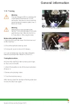
Страница 33: ...ly during transportation longtime storage and maintenance Picture 1 Wait min 60 sec after the engine is stopped before turning off the main switch Warning Under no circumstances should the main switch be used during normal engine operation 1 9 Electrical components continued The rear end fuses and relays functions Relay Function K1 Main Relay Lights K2 Main Relay Valves K3 ECU Main Relay K4 Glow P...

Страница 34: ...der to avoid compressor damage Backrest adjustment Move the locking lever 4 upwards and adjust the backrest angle When you have finished adjusting the backrest the locking lever must be locked into the desired position Lumbar support Adjust the curvature of the backrest cushion by turning the adjustment knob 3 Picture 3 0 No curvature 1 Maximum curvature at the top 2 Maximum curvature at the botto...

Страница 35: ...he button Picture 1 Air conditioning To cool down the cabin switch on the air conditioning and adjust the cabin fan speed on the keypad located on the armrest NB The air conditioning unit and the cabin filter must be checked cleaned once a year Cabin ventilation The nozzles performing the ventilation are located at different places in the cabin under the seat and under the roof Picture 2 3 4 NB To...

Страница 36: ...ity Ranger 3070 Do not connect trailers with a brake assist system to City Ranger 3070 Connecting trailers Coupling connect the trailer to the coupling and make sure that the connection lock is activated Lift the support wheel on the trailer Picture 1 NB If the trailer is fitted with brakes remember to attach the security wire on the trailer to the coupling Lights To control the lights of the trai...

Страница 37: ...arking brake 1 Remove the right side cover from the rear part of the machine 2 Close the hydraulic parking valve 3 Pump with lever minimum 50 strokes 4 It can be necessary to pump more strokes to keep the parking brake released Picture 2 Towing the machine Only tow the machine a few metres just enough to move it out of traffic 1 Attach the towline to one of the towing devices Picture 1 2 Release t...

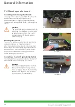
Страница 38: ...ttachments To mount or remove an attachment refer to the operator s manual for the attachments After mounting the attachment make sure that the setting within the display keyboard matches the attachment mounted on the vehicle Check display and chosen attachment s if not sure before starting any operation Connecting a trailer with hydraulic tip Option The hydraulic hoses are connected at the rear o...

Страница 39: ...Operator s manual ...

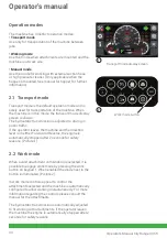
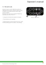
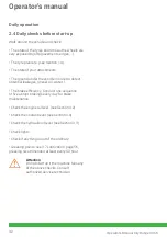
Страница 40: ... in public traffic If the operator leaves the machine and the direction lever is in either Forward or Reverse the engine is automatically stopped after 2 seconds for safety reasons Picture 1 2 2 Work mode When a valid attachment combination is selected it is possible to engage work mode by pressing the work button on keypad 1 When enabled the diode next to the button is illuminated Picture 2 In wo...

Страница 41: ...g in order to use external suction hose or high pressure washer Manual mode can only be engaged if following requisites are valid Picture 1 A hopper is mounted and selected in display The machine is set in parking Parking brake is active and without errors Verify that the parking symbol is shown in the display Manual mode button Operator s manual ...

Страница 42: ...ntial leakages diesel oil water The brake efficiency Conduct one sequence of five abrupt brakings every day for brake maintenance Check the engine oil level see Section 3 2 Check the coolant level see section 3 4 Check the hydraulic oil level see Section 3 3 Check lights Check if anything is out of the ordinary Greasing points see 3 7 Lubrication page 56 greasing recommended at least every 50 hour...

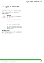
Страница 43: ...y dirt Attention Do not spray cold water at hot parts of the machine Do not spray water into the engine compartment directly or through coolers or cooling fan Do not use any organic solvents Do not use high pressure washing on the cabin sealings under the roof and around the doors Recommendation Clean the machine on a regular daily basis Store tools and auto shampoo Dose auto shampoo as described ...

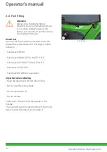
Страница 44: ... fuel specification for this engine listed following Fuel diesel EN590 Fuel diesel ASDM D975 GRADE 1D S15 Fuel diesel ASTM D975 GRADE 2D S15 Fuel diesel JIS K2204 Fuel diesel BS 2869 or equivalent Important when refueling Keep the area free from dirt when filling Do not overfill your fuel tank Do not spill diesel oil Do not smoke Fuel level is shown on the fuel gauge in the display The fuel tank c...

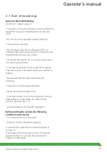
Страница 45: ...raking distance of your vehicle increases when the road is wet and or when your vehicle is loaded Be aware of the steering sensitivity and reactivity Always put on the safety seat belt Never drive with an open door If an alarm lamp is on or flashing when driving please stop in a safe place and refer to this manual see Section 1 7 Always adhere to local traffic legislation Before starting the vehic...

Страница 46: ...arking brake is automatically released when the Direction switch is set to F or R Likewise automatically engaged in parking P 5 Press on the drive pedal to achieve desired speed Picture 3 Note When the machine is in transport mode the drive pedal controls engine rpm In work mode the engine rpm is fixed Braking For braking there are two possibilities 1 Slowly release the drive pedal engine brake It...

Страница 47: ...key back to the key release position counterclock wise When the key is in key release position the key can be removed Remark When the Direction switch is in P position the parking brake will activate automaticly Attention Check that the parking brake indicator is shown in the display Picture 1 Attention When the engine is OFF the parking brake will activate automaticly Parking brake Operator s man...

Страница 48: ...n order to ensure self lubrication Then slowly operate all system functions several times at low load in order to warm up the entire system as uniformly as possible In the same time slowly swivel the traction pump outwards Continuous flushing is necessary in all components in order to prevent temperature shocks All system functions must be operated slowly several times at low load until the entire...

Страница 49: ...nsport securing rings and the trailer hitch of the vehicle Picture 1 2 3 4 Attention Remember to secure doors panels etc before transport and taking off Eventually reverse the machine on to the trailer for better weight distribution between vehicle and trailer Anchoring at the front Straps at the front Anchoring at the rear hitch Straps at the rear Operator s manual ...

Страница 50: ...Service and maintenance ...

Страница 51: ... m m m Engine oil filter 2 l l l l l l 3 8 Hoses and collars m m m m m m Radiator t Engine valve lash m m m Fan clearance m m m m m Alternator m Engine crankcase breather l l Engine mounts m Turbocharger m m Starter m Battery electrolyte level m m m m m m Coolant temperature regulator l Glow plugs l Engine water pump m Radiator pressure cap t Brake fluid 3 m m m m m m l 3 5 Hydraulic hoses m m m m...

Страница 52: ...lic fittings tightening m m m m Tyre condition and pressure m 1 4 Door adjustment m m m Grease nipples n n n n n n n 3 7 1 Check glycol level every 500 hours and before winter 2 Replace the engine oil every 500 hours and at least once a year 3 Replace the brake fluid every 3000 hours and at least once every two years 4 Replace the hydraulic oil every 1500 hours 5 Clean the drum brakes trim every 5...

Страница 53: ...tes after stopping the engine in order to allow the engine oil to return to the oil tank 3 Take the dipstick out dry and put back Picture 2 4 Take the dipstick out again to read the oil level The oil level must be between MAX and MIN on the dipstick Picture 2 5 In case of lack of oil remove the filler cap on the engine Add oil wait a few minutes and check the level again Picture 3 Engine oil fille...

Страница 54: ...th a new gasket 5 Remove the oil filter with a suitable tool Picture 3 6 Clean the sealing surface of the cylinder block or the oil cooler Attention Do not fill the oil filters with oil before installing them This oil would not be filtered and could be contaminated Contaminated oil can cause accelerated wear to engine components 7 Apply clean engine oil to the new oil filter seal 8 Install the new...

Страница 55: ... drain back to the sump for a minimum of 10 minutes 12 Take the dipstick out wipe clean and put back 13 Take the dipstick out again to read the oil level 14 The oil level must be between MAX and MIN on the dipstick Picture 1 15 In case of lack of oil remove the filler cap on the engine Add oil wait a few minutes and check the level again 3 3 Hydraulic oil Checking the hydraulic oil level 1 The hyd...

Страница 56: ... drain pan Picture 1 2 3 After drainage clean the oil drain plug and put them back with new gasket 4 To refill the hydraulic oil tank unscrew the cap and pour in hydraulic oil while observing the level glass Attention Only use new and correct hydraulic oil Attention Used oil is to be delivered at an approved waste disposal facility or site Hydraulic oil drain plug Hydraulic oil drain plug Service ...

Страница 57: ... is under pressure Never remove the cap when the motor is hot as hot water can escape and cause serious burns Wait for at least ten minutes after the motor has been switched off and then slowly remove the coolant tank cap Checking the coolant level 1 The coolant tank is located over the engine fan Picture 1 2 An engine coolant alarm appears if the coolant level is too low See section 1 17 3 To adj...

Страница 58: ...ing the coolant hose in the bottom of the left side radiator Picture 1 3 Drain the coolant in the container then connect the sleeve 4 Remove the coolant tank cap and completely fill the system with coolant The coolant tank must be full Coolant components 50 of ANTIFREEZE 50 of water Always use the recommended antifreeze or equivalent 5 Put back the radiator cap 6 Turn on the engine and let it idle...

Страница 59: ... 2 Warning Avoid any contact with brake fluid on skin or eyes Seek medical attention if contact between eyes and brake fluid happens 3 6 Windscreen washer liquid The windscreen washer tank is located on cabin left side Picture 3 To add windscreen washer liquid unscrew the cap Only use washer liquid that have frost protection properties Attention Used Windscreen washer liquid is to be delivered at ...

Страница 60: ...hould be stored in near proximity of the machine in order to minimize the chance of lubrication being skipped Greasing point number Description Acces 1 2 A Frame cylinder right From underneath 3 4 A Frame cylinder left From underneath 5 Steering cylinder right front From underneath 6 Steering cylinder right rear From right side 7 Steering cylinder left front From underneath 8 Steering cylinder lef...

Страница 61: ...s Picture 2 3 Loosen the straps to retrieve filter elements If the air filter is dirty Remove the primary air cleaner element Picture 3 Clean the inside of the air cleaner cover and body with a clean dry cloth Clean the primary air cleaner element using a vacuum cleaner or low pressure compressed air pressure 207kPa The secondary air cleaner element is not serviceable or washable Picture 4 It shou...

Страница 62: ...a proper tool remove the filter Ensure that any fluid is drained into a suitable container 5 Empty the filter for liquids into a suitable container The used filter must be disposed of in an environmentally correct way 6 Check that the seal is in place 7 Install a new fuel filter 8 The fuel system will need to be primed after the new filter is installed 9 Turn the keyswitch to the ON position for 2...

Страница 63: ...sure that the fuel in the filter does not drain completely out If it does remove it fill it manually and then repeat the bleeding operation Fuel decanter filter replacement Check the status of the fuel decanter filter Picture 1 If the element is clogged proceed as follows 1 Turn off the engine and remove the ignition key 2 Let the engine cool down adequately to avoid being burnt 3 Prepare a contai...

Страница 64: ...driver s seat by unscrewing the finger screws Picture 1 2 2 Pull out filter 3 Insert new filter 4 Mount cover plate Recirculation filter 1 Move the driver s seat to its most forward position 2 The filter is located behind the seat Picture 3 4 3 Unclick the filter and discard it 4 Click new filter Cabin filter behind seat Recirculation filter behind seat Service and maintenance ...

Страница 65: ...ure 2 3 If the fins are still clogged clean them with a brush and kerosene and dry with compressed air 6 Bar Picture 3 Air conditioning condenser To ensure the smooth operation of the condenser regularly clean the air conditioning condenser with an air compressor gun 1 Clean the fins with compressed air 6 Bar If necessary point the compressed air in the opposite direction of the cooling air Pictur...

Страница 66: ... the center of the belt between the alternator compressor and the crank shaft pulley and check the belt tension The correct tension for a new belt is 400 N to 489 N The correct tension for a used belt that has been in operation for 30 minutes or more at the rated speed is 267 N to 356 N Picture 1 Alternator and water pump belt Check the belt for wear and tear also check that it is properly tension...

Страница 67: ...he arrow Picture 1 3 Once the jack is well positioned loosen the wheel bolts 4 Raise the jack until the wheel is a few centimetres above the ground Watch out the vehicle stability when raising 5 Unscrew and change the wheel Screw the bolts but do not tighten 6 Lower the jack and then tighten the wheel bolts to torque 120 Nm Attention After 20 hours of use tighten the wheel bolts again to 120 Nm Wh...

Страница 68: ...ce and provide the serial number of your City Ranger 3070 You can read it on the information plate of your vehicle Picture 1 2 3 12 Storage If long term storage is needed make sure to Clean the machine Drain fuel tank Turn main switch to off position Always store in a dry environment Make sure normal maintenance has been carried out prior to storage After storage Fill the fuel tank with fresh dies...

Страница 69: ...Conditions ...

Страница 70: ...vered by the warranty 3 All inquiries concerning the warranty are to be addressed to the distributor from whom the machine was purchased 4 This warranty does not cover faults and defects which cannot be traced back to defects in material or production errors 5 This warranty is valid for persons who have legally acquired the machine within the warranty period 6 In the event of failure to perform an...

Страница 71: ...Egholm A S 4 3 Disposal When many years from now your City Ranger 3070 has reached the end of its working life it should be disposed of in a responsible manner that conforms to relevant disposal regulations 1 Used hydraulic oil motor oil diesel oil coolant and AC coolant are to be delivered at an approved waste disposal facility or site 2 Remove the plastic and rubber parts and dispose of them in ...

Страница 72: ...Wearing parts ...

Страница 73: ...73 Operator s Manual City Ranger 3070 5 1 Wearing parts Wearing parts please contact your local Egholm dealer Wearing parts ...

Страница 74: ...74 Operator s Manual City Ranger 3070 Notes ...

Страница 75: ...75 Operator s Manual City Ranger 3070 Notes ...

Страница 76: ...Egholm A S Transportvej 27 7620 Lemvig Denmark T 45 97 81 12 05 www egholm eu info egholm dk 55911946 A0 01 EN ...

Отзывы: