A533-23-880 Issue C
Page 78
© Edwards Limited 2009. All rights reserved.
Edwards and the Edwards logo are trademarks of Edwards Limited.
Pump display terminal menus and display formats
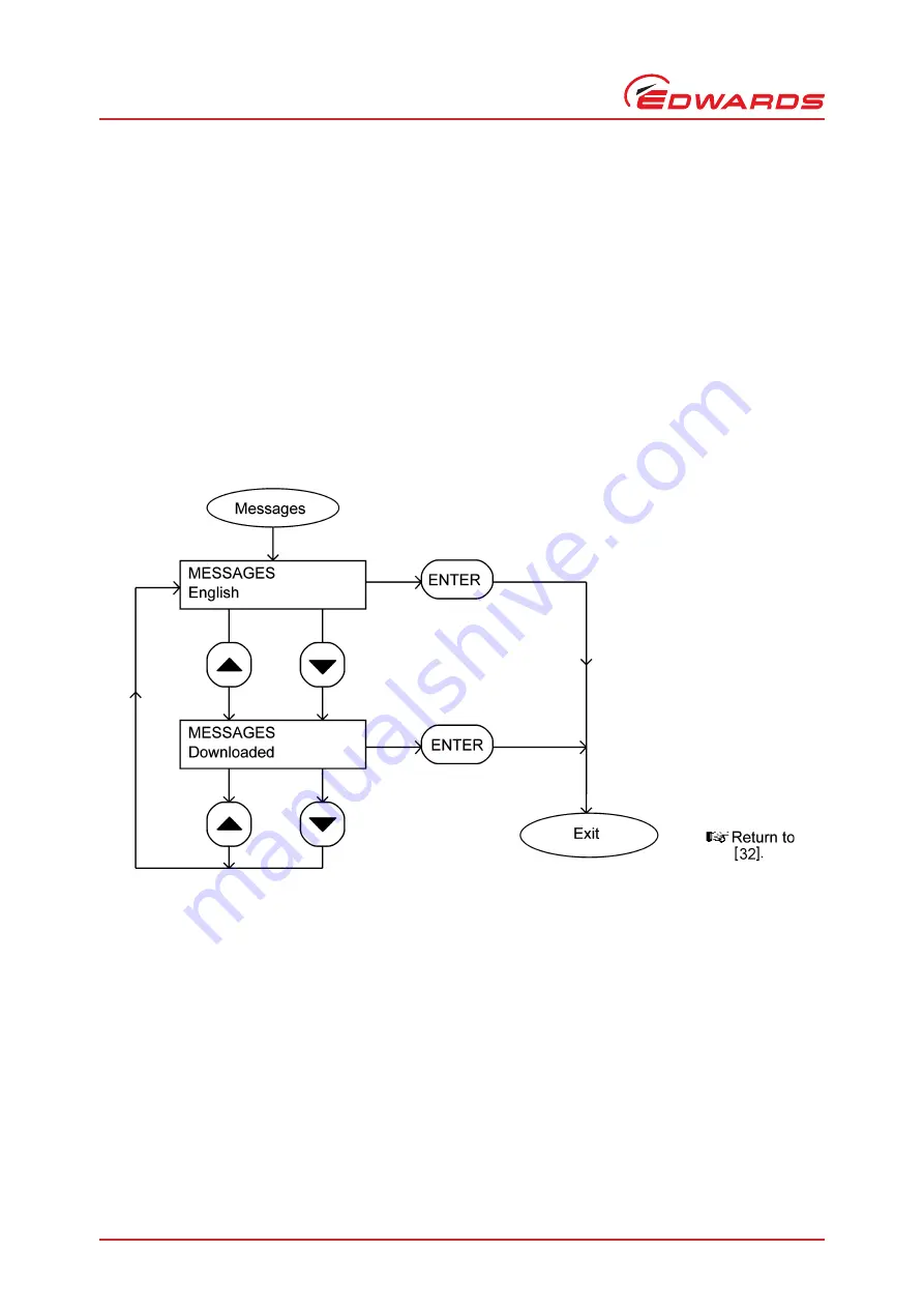
Figure 45 - Message menu
Страница 1: ...A533 23 880 Issue C Original Instruction Manual iF1800 Rapid Loadlock Dry Pumping Systems...
Страница 2: ...ssors and Vacuum Pumps Safety Requirements Vacuum Pumps EN61010 1 2001 Safety Requirements for Electrical Equipment for Measurement Control and Laboratory Use General Requirements EN 61326 1 2006 Elec...
Страница 3: ...System Setup Password The setup password for this equipment is preset as follows SETUP PASSWORD 202 You can remove this sheet from the instruction manual and retain it in a safe place to prevent unaut...
Страница 4: ......
Страница 5: ...unctions 10 1 11 1 Priority of control 10 1 11 2 Setpoints warning and alarm conditions 13 1 11 3 Safety sensors 13 1 12 Pump Display Terminal 13 1 13 Drip tray 14 1 14 Anchor brackets 14 1 15 Labels...
Страница 6: ...ommission the iF system 49 3 19 1 Switch on an iF1800 system 49 4 Pump display terminal menus and display formats 51 4 1 Introduction 51 4 2 General operation 51 4 3 The CANCEL button 52 4 4 Display t...
Страница 7: ...113 8 3 1 Regrease Spares 113 8 4 Ordering accessories 114 8 4 1 Exhaust Temperature Sensor 114 8 4 2 Active gauge connection kit 114 8 5 Other accessories 114 8 5 1 iF Communications Module 114 8 5...
Страница 8: ...l of the Pump Display Terminal 52 22 Menu logic 55 23 Switch on menu 56 24 Switch off menu 57 25 Normal Menu 58 26 status menu sheet 1 of 2 59 27 Status menu sheet 2 of 2 60 28 Control menu 61 29 setu...
Страница 9: ...cs module default setpoints 28 9 Gas module default setpoints High gas configuration 28 12 Checklist of components 33 13 Pins in the iF Tool Interface Module connector plug 45 14 Pins in the electrica...
Страница 10: ...This page has been intentionally left blank A533 23 880 Issue C Page vi Edwards Limited 2009 All rights reserved Edwards and the Edwards logo are trademarks of Edwards Limited...
Страница 11: ...d the abbreviation slm is used to mean standard l min 1 this is a flow of 1 l min 1 at an ambient temperature of 0o C and a pressure of 1013 mbar 1 013 x 105 Pa Note The content of this manual may cha...
Страница 12: ...oil into the system being evacuated The iF1800 system has an FDP200 dry pump with an HMB1800 mechanical booster pump fitted to the inlet of the FDP200 pump The FDP200 pump is referred to as the FDP p...
Страница 13: ...otors forms with the casing a transference space for gas These rotors which rotate without metal to metal contact are held in correct phase relation by a pair of timing gears These timing gears and th...
Страница 14: ...will cause the iF system to be shut down at the appropriate alarm pressure The front panel has three pressure status LEDs Figure 6 items 3 5 and 6 These LEDs indicate whether the nitrogen supply press...
Страница 15: ...to shut down if the temperature exceeds 60oC A motor protection thermistor and a snap switch are fitted to the pump motor The thermistor operates at 130o C and the snap switch at 155oC Both are connec...
Страница 16: ...rge 9 Gas Module manifold 10 Variable restrictor 3 4 dilution purge 11 Variable restrictor 2 3 cooling purge 12 Variable restrictor inlet purge 13 Variable restrictor shaft seals purge 14 Variable res...
Страница 17: ...e self resetting fuses in the Electrics Box protect the d c electrical supplies to the network Refer to Figure 4 detail C The rear panel of the Electrics Box has the following lamp and connections Pow...
Страница 18: ...ace Module accessories The following sensors are connected to the Control Module FDP pump body temperature sensor HMB pump temperature sensor Exhaust temperature sensor if fitted Water flow switch FDP...
Страница 19: ...th ground stud 20 Solenoid valve power supply 21 Not used 22 Not used 23 Pump shutdown thermistor 24 Not used 25 Emergency stop switch 26 RJ12 connector for PDT 27 Cooling water solenoid valve 28 HMB...
Страница 20: ...Running LED 8 This green LED is on when the iF pumps are operating Alarm LED 9 This red LED is on when an alarm condition exists refer to Section 1 11 2 Warning LED 10 This yellow LED is on when a war...
Страница 21: ...x 1 Rear cover 2 Cooling water outlet 3 Cooling water inlet 4 Nitrogen inlet 5 Position of Active Gauge connector 6 RF earth ground stud 7 Power on lamp 8 Tool Interface Module connector 9 LON interfa...
Страница 22: ...ectrics Box 5 FDP pump motor terminal box 6 Cooling water solenoid valve 7 FDP pump shut down thermistor 8 FDP pump water flow switch 9 Gas Module 10 FDP pump body temperature sensor 11 FDP oil level...
Страница 23: ...Section 5 2 Refer to Section 2 for the default setpoints 1 11 3 Safety sensors The iF system has a number of safety sensors which are connected to the relay interlock circuit If any of the safety sen...
Страница 24: ...efer to Section 8 5 7 for ordering information Figure 6 Controls and indicators on the dashboard 1 13 Drip tray The drip tray is fitted to the bottom of the iF frame refer to Figure 1 and allows the c...
Страница 25: ...ogen purge gas to the dry pumping system is too low Table 2 Explanation of menu buttons Button LED Colour Button Use Normal Green Press this button to select the Normal display see above Control Green...
Страница 26: ...Explanation of LED s LED LED Colour Meaning ALARM Red This LED shows when an alarm condition exists WARNING Amber This LED shows when a warning condition exists LOCAL CONTROL Green This LED is on when...
Страница 27: ...6 Oil 2 Caution Do not overfill with oil 3 HMB Information Warning Risk of High Temperature symbol 4 Direction of Rotation Arrow 5 HMB Motor Rating Information 6 Warning Risk of Electric Shock symbol...
Страница 28: ...cals Enclosed 5 Warning Disconnect mains supply before removing Electric Box covers 6 Warning Risk of Electric Shock 7 System Information Warning Risk of High Temperature Symbol 8 Protective Earth sym...
Страница 29: ...ent operating humidity 90 RH Noise level measured at 1 m from the pump with enclosure panels fitted refer to Table 4 Mass refer to Table 4 Centre of mass mass distribution refer to Figure 12 Pumping s...
Страница 30: ...2009 All rights reserved Edwards and the Edwards logo are trademarks of Edwards Limited Technical Data Figure 10 iF1800 dimensions mm A Side view B Plan view 1 Inlet 2 Outlet as supplied 3 Air extrac...
Страница 31: ...Negative Temperature Coefficient thermistor Opening temperature 60 3 C Closing temperature 50 4 C Thermocouples K type class 1 FDP and HMB motor protection thermistor type Positive temperature coeffi...
Страница 32: ...y quality Acidity 6 5 to 8 0 Hardness 100 ppm Resistivity 1 k cm 1 Solids turbidity 100 ppm With cooling water supply temperature of 20 C and a flow rate of 6 l min 1 End bearings Quantity 100 g Recom...
Страница 33: ...rks of Edwards Limited Technical Data A533 23 880 Issue C Figure 12 Centre of mass dimensions mm and mass distribution 1 Levelling foot 2 Levelling foot 3 Levelling foot 4 Levelling foot 5 Centre of m...
Страница 34: ...sue C Page 24 Edwards Limited 2009 All rights reserved Edwards and the Edwards logo are trademarks of Edwards Limited Technical Data Figure 13 Typical pumping speed and pump power curves for an iF1800...
Страница 35: ...included for information only You cannot change these fuses a Edwards service engineer must change these fuses 30 A 600 V Class J F2 30 A 600 V Class J F3 30 A 600 V Class J F4 20 A 600 V Class J F5...
Страница 36: ...ansducer accuracy 0 6 psi 4 1 x 10 2 bar 4 1 x 10³ Pa at 6 psig 1 4 bar absolute 1 4 x 10⁵ Pa Flow transducer accuracy 3 0 slm 5 x 10³ Pa l s 1 Table 6 Nitrogen Purge flow rates High gas configuration...
Страница 37: ...n completion of its useful life 2 11 Default setpoints The default setpoints are shown in Tables 7 to 9 Where there is an ADJ adjust entry in these tables this specifies that the setpoints are usually...
Страница 38: ...it Default setpoint values Low alarm Low warning High warning High alarm FDP pump temperature C ADJ ADJ 75 85 FDP motor cooling water return temperature C ADJ ADJ 55 ADJ HMB1800 pump temperature C ADJ...
Страница 39: ...LR type 4 way Exhaust Gas Management interface 6 pin DIN 3 Common 4 Normally Closed 5 Normally Open iF Tool Interface Module connector XLR type 6 way Nitrogen supply connector 1 4 inch Tube fitting Wa...
Страница 40: ...A533 23 880 Issue C Page 30 Edwards Limited 2009 All rights reserved Edwards and the Edwards logo are trademarks of Edwards Limited This page has been intentionally left blank...
Страница 41: ...th nitrogen for 15 minutes before you start installation work Disconnect the other components in the process system from the electrical supply so that they cannot be operated accidentally Electrical n...
Страница 42: ...cuum system 3 9 Connect the iF exhaust outlet to your exhaust extraction system 3 10 Connect to your factory extraction system optional 3 11 Connect the nitrogen supply 3 12 Leak test the system 3 13...
Страница 43: ...try to lift the iF system by hand refer to Table 4 for the mass of the iF system 6 Inspect the iF system If the iF system or any other item is damaged notify your supplier and the carrier in writing w...
Страница 44: ...Limited INSTALLATION Figure 14 Remove the iF system from the pallet 1 Nw40 clamp 1 Nitrogen pipeline fitting 1 Module connector terminator plug Table 12 Checklist of components Quantity Description C...
Страница 45: ...left hand side panel 6 to support it and use a flat head screwdriver to release the 3 quarter turn catches 5 Swing the top of the panel out slightly and lift out the panel so that the slots in the bo...
Страница 46: ...All rights reserved Edwards and the Edwards logo are trademarks of Edwards Limited INSTALLATION Figure 16 Remove refit the enclosure panels 1 Top panel 4 Catches on rear of item 1 5 Catches 6 Left han...
Страница 47: ...the pump may be damaged 3 6 1 iF1800 Systems The iF1800 systems are supplied with both the FDP and HMB pumps filled with oil However we recommend that you check the FDP and HMB oil levels as described...
Страница 48: ...flange of the iF system to your process system refer to Section 3 15 2 for more information When you connect your iF system to your vacuum system take note of the following To get the best pumping spe...
Страница 49: ...onnecting to the rear bulkhead cover drip tray 27 and exhaust enclosure top plate undo and remove the clamp and O ring 22 and 21 which secures the check valve to the elbow 20 retain the check valve fo...
Страница 50: ...rks of Edwards Limited INSTALLATION Figure 17 Fit the pump display terminal A Remove the blanking panel B Fit the Pump Display Terminal 1 Blanking panel 2 Dashboard 3 Pump Display Module connector 4 C...
Страница 51: ...are not introduced into the nitrogen supply Use the Tube fittings in the fitting kit to connect your nitrogen pipeline to the iF system use the Tube fittings as described in Section 6 2 3 12 Leak test...
Страница 52: ...e 42 Edwards Limited 2009 All rights reserved Edwards and the Edwards logo are trademarks of Edwards Limited INSTALLATION Figure 18 Leak test port positions 1 HMB pump 2 FDP pump 3 Leak test port blan...
Страница 53: ...Limited INSTALLATION A533 23 880 Issue C Figure 19 Connect the electrical supply cable to the connector mating half 1 Pin 1 Phase 1 2 Pin 2 Phase 2 3 Pin 3 Phase 3 4 Earth ground screw 5 Strain releif...
Страница 54: ...tor on the rear of the iF system Figure 4 item 8 If you do not you will not be able to operate the iF system If required you can connect your own control equipment to the iF system to shut down the iF...
Страница 55: ...or your electrical supply Reconfigure if necessary 4 Refit the cover 4 and secure with the two screws 5 Table 13 Pins in the iF Tool Interface Module connector plug Pin s Use 1 and 2 3 and 4 5 6 Linke...
Страница 56: ...rights reserved Edwards and the Edwards logo are trademarks of Edwards Limited INSTALLATION Figure 20 Reconfigure the iF system for your electrical supply 1 iF system 2 Electrics box 3 Cover 4 Screw 5...
Страница 57: ...he earth ground wire of the cable to one of the two earth ground screws 4 on the side of the connector block 8 4 Refit the cover 7 to the connector block 8 then tighten the strain relief bush 5 5 Fit...
Страница 58: ...a safe temperature Restoring the cooling water supply whilst the pump is in operation may result in FDP seizure Notes For optimum water cooling ensure that your cooling water supply and return hoses...
Страница 59: ...d check that the power OK LED Figure 6 item 7 goes on If the LED does not go on refer to Section 6 to determine the cause of the fault 2 Switch on the cooling water and nitrogen supplies 3 Ensure that...
Страница 60: ...d the Edwards logo are trademarks of Edwards Limited INSTALLATION If the pressure is decreasing continue at Step 7 7 After you have commissioned the iF system If you want to continue to operate the iF...
Страница 61: ...l Status Control and Setup This symbol is used for the up and down buttons and for the on and off buttons This symbol is used for the two line display on the PDT This symbol is a submenu box a submenu...
Страница 62: ...meters the defaults are FDP current consumption and power consumption When you change passwords in the Setup and Service menus Figures 34 and 35 and before you press the ENTER button if you press CANC...
Страница 63: ...e when you enter a password digit if the digit is 0 and you press the down button the digit will change to 9 if the digit is 9 and you press the up button the digit will change to 0 4 6 Timeout As sup...
Страница 64: ...urge on the bottom line 6 Press the down button six times or press the up button five times the display will then show SETUP MENU on the top line and Units on the bottom line 7 Press the ENTER button...
Страница 65: ...Edwards Limited 2009 All rights reserved Page 55 Edwards and the Edwards logo are trademarks of Edwards Limited Pump display terminal menus and display formats A533 23 880 Issue C Figure 22 Menu logic...
Страница 66: ...33 23 880 Issue C Page 56 Edwards Limited 2009 All rights reserved Edwards and the Edwards logo are trademarks of Edwards Limited Pump display terminal menus and display formats Figure 23 Switch on me...
Страница 67: ...wards Limited 2009 All rights reserved Page 57 Edwards and the Edwards logo are trademarks of Edwards Limited Pump display terminal menus and display formats A533 23 880 Issue C Figure 24 Switch off m...
Страница 68: ...533 23 880 Issue C Page 58 Edwards Limited 2009 All rights reserved Edwards and the Edwards logo are trademarks of Edwards Limited Pump display terminal menus and display formats Figure 25 Normal Menu...
Страница 69: ...Limited 2009 All rights reserved Page 59 Edwards and the Edwards logo are trademarks of Edwards Limited Pump display terminal menus and display formats A533 23 880 Issue C Figure 26 status menu sheet...
Страница 70: ...880 Issue C Page 60 Edwards Limited 2009 All rights reserved Edwards and the Edwards logo are trademarks of Edwards Limited Pump display terminal menus and display formats Figure 27 Status menu sheet...
Страница 71: ...dwards Limited 2009 All rights reserved Page 61 Edwards and the Edwards logo are trademarks of Edwards Limited Pump display terminal menus and display formats A533 23 880 Issue C Figure 28 Control men...
Страница 72: ...880 Issue C Page 62 Edwards Limited 2009 All rights reserved Edwards and the Edwards logo are trademarks of Edwards Limited Pump display terminal menus and display formats Figure 29 setup menu sheet...
Страница 73: ...s Limited 2009 All rights reserved Page 63 Edwards and the Edwards logo are trademarks of Edwards Limited Pump display terminal menus and display formats A533 23 880 Issue C Figure 30 setup menu sheet...
Страница 74: ...880 Issue C Page 64 Edwards Limited 2009 All rights reserved Edwards and the Edwards logo are trademarks of Edwards Limited Pump display terminal menus and display formats Figure 31 setup menu sheet...
Страница 75: ...rds Limited 2009 All rights reserved Page 65 Edwards and the Edwards logo are trademarks of Edwards Limited Pump display terminal menus and display formats A533 23 880 Issue C Figure 32 Run til crash...
Страница 76: ...A533 23 880 Issue C Page 66 Edwards Limited 2009 All rights reserved Edwards and the Edwards logo are trademarks of Edwards Limited Pump display terminal menus and display formats Figure 33 Units menu...
Страница 77: ...rds Limited 2009 All rights reserved Page 67 Edwards and the Edwards logo are trademarks of Edwards Limited Pump display terminal menus and display formats A533 23 880 Issue C Figure 34 Normal display...
Страница 78: ...880 Issue C Page 68 Edwards Limited 2009 All rights reserved Edwards and the Edwards logo are trademarks of Edwards Limited Pump display terminal menus and display formats Figure 35 Service menu sheet...
Страница 79: ...Limited 2009 All rights reserved Page 69 Edwards and the Edwards logo are trademarks of Edwards Limited Pump display terminal menus and display formats A533 23 880 Issue C Figure 36 Service menu shee...
Страница 80: ...533 23 880 Issue C Page 70 Edwards Limited 2009 All rights reserved Edwards and the Edwards logo are trademarks of Edwards Limited Pump display terminal menus and display formats Figure 37 Serial menu...
Страница 81: ...ards Limited 2009 All rights reserved Page 71 Edwards and the Edwards logo are trademarks of Edwards Limited Pump display terminal menus and display formats A533 23 880 Issue C Figure 38 Zero sensor m...
Страница 82: ...9 Gas valve control menu Notes You should only use this menu if you have been suitably trained by Edwards Service Personnel If necessary contact Edwards or your supplier to arrange suitable training T...
Страница 83: ...Limited 2009 All rights reserved Page 73 Edwards and the Edwards logo are trademarks of Edwards Limited Pump display terminal menus and display formats A533 23 880 Issue C Figure 40 manual menu sheet...
Страница 84: ...880 Issue C Page 74 Edwards Limited 2009 All rights reserved Edwards and the Edwards logo are trademarks of Edwards Limited Pump display terminal menus and display formats Figure 41 Manual menu sheet...
Страница 85: ...Limited 2009 All rights reserved Page 75 Edwards and the Edwards logo are trademarks of Edwards Limited Pump display terminal menus and display formats A533 23 880 Issue C Figure 42 Manual menu sheet...
Страница 86: ...0 Issue C Page 76 Edwards Limited 2009 All rights reserved Edwards and the Edwards logo are trademarks of Edwards Limited Pump display terminal menus and display formats Figure 43 View status menu she...
Страница 87: ...imited 2009 All rights reserved Page 77 Edwards and the Edwards logo are trademarks of Edwards Limited Pump display terminal menus and display formats A533 23 880 Issue C Figure 44 View status menu sh...
Страница 88: ...533 23 880 Issue C Page 78 Edwards Limited 2009 All rights reserved Edwards and the Edwards logo are trademarks of Edwards Limited Pump display terminal menus and display formats Figure 45 Message men...
Страница 89: ...mited 2009 All rights reserved Page 79 Edwards and the Edwards logo are trademarks of Edwards Limited Pump display terminal menus and display formats A533 23 880 Issue C Figure 46 Warning and alarm me...
Страница 90: ...A533 23 880 Issue C Page 80 Edwards Limited 2009 All rights reserved Edwards and the Edwards logo are trademarks of Edwards Limited This page has been intentionally left blank...
Страница 91: ...ly understand the use of the Pump Display Terminal menus and buttons before you operate the iF system Refer to Section 4 which fully defines the menus the use of the buttons and the display formats No...
Страница 92: ...in either o C or o F Use the Setup Units Temperature menu to change the temperature display units Pressures measured by an optional Active Gauge connected to the iF system can be shown on the Pump Dis...
Страница 93: ...tch on the following actions will occur with a small time delay between each action The LED on the On button on the Pump Display Terminal will start to flash The FDP pump will be switched on The LED o...
Страница 94: ...e information that can be displayed up to two items of information at a time is shown in Table 17 5 8 Warning and alarm indications Notes Refer to Section 6 for a full list of the warning and alarm me...
Страница 95: ...ay Terminal goes off If you need to shut down the iF system quickly use the Fast shut down option When you select Fast shut down the following actions will occur with a small time delay between each a...
Страница 96: ...HMB pump current consumption HMB pump power consumption Total running time Process running time Process cycles iF cycles HMB pump temperature FDP pump motor water manifold surface temperature Exhaust...
Страница 97: ...use the Switch On Booster Pump menu to restart the HMB pump after the alarm condition has cleared 5 13 Restart the iF system after an emergency stop or automatic shut down Note If the iF system has a...
Страница 98: ...ontrol the operation of iF system components separately Use the Setup Service Manual Gas Module menu to control the operation of the Gas Module that is turn the nitrogen supply gas ballast and inlet p...
Страница 99: ...it lifting bolts or start maintenance work Vent and purge the iF system with nitrogen before you start any maintenance work Isolate the iF system and other components in the process system from the el...
Страница 100: ...be fitting You must know how to correctly fit and tighten tube fittings in order to prevent gas leaks use the procedures in the following sections 6 2 1 Fit a tube fitting 1 Refer to Figure 46 detail...
Страница 101: ...ecure tighten any loose connections Inspect all electrical cables and connectors for damage replace any cables and connectors that are damaged 5 Check that all process and exhaust connections are secu...
Страница 102: ...for example a long bottle brush and a cleaning solution suitable for the deposits to clean the exhaust silencer outlet and continue at Step 7 If you need to remove the exhaust silencer from the pump t...
Страница 103: ...ge any remaining deposits then wash the silencer body and top flange assembly with steam or water Finally bead blast the internals of the silencer Protect all sealing faces the drilled and tapped hole...
Страница 104: ...le for the deposits to clean the valve body and the fluoroelastomer ball If necessary replace the fluoroelastomer ball 3 Inspect the O ring groove and the flange sealing faces for damage re finish if...
Страница 105: ...Figure 1 Check that the oil level is between the MAX and MIN marks on the bezel of the HMB oil level sight glass 5 If the oil level is above the MAX mark drain excess oil from the pump as described in...
Страница 106: ...l viewing port is provided on the right hand side panel viewed from the front of the system These should be used as an indication only for an accurate oil level assessment use the following procedure...
Страница 107: ...Figure 1 Check that the oil level is between the MAX and MIN marks on the bezel of the FDP oil level sight glass 11 If the oil level is above the MAX mark drain excess oil from the pump as described...
Страница 108: ...8 and replace it with a new O ring 10 Refit the filler plug 8 11 Refit the right hand side enclosure panel 6 10 Change the HMB pump oil Refer to the warnings and cautions in Section 6 7 1 Shut down th...
Страница 109: ...ront bulkhead from the iF system taking care not to damage the looms or the gas pipe turrets 12 Remove the two bearing covers from the front of the FDP 13 Use clean lint free cloth or a plastic or woo...
Страница 110: ...the Pump Display Terminal display viewing angle If the display Figure 7 item 2 is difficult to see use the following procedure to adjust the display viewing angle 1 Refer to Figure 17 Remove the Pump...
Страница 111: ...r maintenance If you want to remove the iF system from its operating location and move it to another location where you will do maintenance use the following procedure 1 Purge the iF system and shut d...
Страница 112: ...ause of the fault and to rectify the fault The first line of a message specifies the fault condition warning or alarm and shows the error number Error numbers are of the form PFF PPFF or PPPFF where P...
Страница 113: ...k in the system or process debris in the pump or the pump motor may have failed Inspect the pipelines and service the pump WARNING 409 DP POWER LOW OPEN CIRCUIT CHECK CONNECTION The electrical power c...
Страница 114: ...lectrical supply and the connections to the iF system If the electrical supply and connections are correct the pump motor may be faulty WARNING 1201 When started no electrical current was drawn by the...
Страница 115: ...in this table WARNING 4013 The shaft seals pressure transducer is not fitted or is disconnected or has failed Check and rectify as necessary WARNING 5113 There is a fault in the ADC analogue to digit...
Страница 116: ...struction manual supplied with the NIM WARNING 12101 There is a fault in the Tool Interface Card in the iF Interface Module Refer to the instruction manual supplied with the iF Interface Module WARNIN...
Страница 117: ...refer to Table 19 ALARM 512 The pump motor has tripped out because the motor windings are too hot either the cooling system has failed or the motor overloaded Either of these faults should have been i...
Страница 118: ...e recommended actions for error number 5709 refer to Table 19 ALARM 5712 DP TEMP HIGH TCV SET HIGH ADJUST TCV Refer to the recommended actions for error number 5711 refer to Table 19 ALARM 17410 SEE M...
Страница 119: ...the request identify and rectify the cause for the failure of the pump s to start or stop then try again b You have tried to open or close one of the gate valves if fitted but the valve has failed to...
Страница 120: ...les since last service Switch on off cycles since last service Gas Module status Gas Module flow transducer total nitrogen purge flow Exhaust pressure sensor Shaft seals purge pressure transducer Cont...
Страница 121: ...ust connections 2 Fit blanking plates to all vacuum inlets and exhaust outlets Place protective covers over the iF services connection points 3 Store the iF system in clean dry conditions until requir...
Страница 122: ...A533 23 880 Issue C Page 112 Edwards Limited 2009 All rights reserved Edwards and the Edwards logo are trademarks of Edwards Limited This page has been intentionally left blank...
Страница 123: ...ported by a world wide network of Edwards Service Centres Each Service Centre offers a wide range of options including equipment decontamination service exchange repair rebuild and testing to factory...
Страница 124: ...ni Gauge APG L Active Pirani Gauge Heated Barocel Capacitance Manometers 10 to 1000 mbar or torr When supplied the Active Gauge Connection Kit is configured for use with an APG MP Active Pirani Gauge...
Страница 125: ...e iF Single Pumpset Monitor allows you to monitor pump parameters and configure the iF system The iF Fabworks allows you to network together all of the iF systems in your installation and to use a PC...
Страница 126: ...llow you to use the Pump Display Terminal further away from the iF system Accessory Item Number Extension cable display interface 3 m D372 07 591 Extension cable display interface 5 m D372 07 592 Exte...