


D.
Heading Input Check
(1) On the WX-PA, select “Continuous Out” on the MODE MENU, then press the MENU/
ENTR button once (so that WX-PA indicates “PAUSED” and not “RUNNING”).
(2) On the WX-PA, press the FLAPS/A button to select top mount antenna configuration
(if not already selected).
(3) On the WX-PA, select a cardinal bearing of 180° and a range of 75 NM.
•
Use F1 and F2 buttons to adjust range and the F3 and F4 buttons to adjust
bearing.
(4) On the WX-PA, with “Continuous Out” still selected on the MODE MENU, press the
MENU/ENTR button once so that WX-PA indication changes from “PAUSED” to
“RUNNING”.
(5) On the left hand GPS 400W (GPS 1), push the MENU button. Highlight CLEAR
STORM DATA? (if not already highlighted), then push the ENT button.
NOTE: Strike RATE will recede then ramp up toward 600 ± 200 strikes per minute
again.
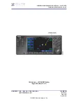
(6) Observe the GPS 400W Lightning display to ensure proper positioning of the test
strikes, based on range and bearing settings on the WX-PA.
(a) Make sure that test strikes appearing on the GPS 400W Lightning display are
plotted at 180 ± 10° and approximately 75 NM.
(7) Make sure that the Strike RATE counter is strikes (600 ± 200 strikes per minute).
(8) With aircraft magnetic heading active, turn the aircraft 45 ±5° to the right.
(9) Make sure that previously plotted discharge points move approximately 45°
counterclockwise (approximately 135° relative on the GPS 400W display).
EA500 Aircraft Maintenance Manual — 06-117751
Temporary Revision No. 34-21
EFFECTIVITY: 0001 - 0008, 0010 - 0050, 0052, 0054 -
0267 PRE SB 500-31-024
34-40-50
CONFIG A
Page 507
Sep 30/20
© 2020 Eclipse Aerospace, Inc.


