Unitech EA500 - устройство сбора данных с широким диапазоном функций. Чтобы узнать больше о его возможностях, скачайте бесплатный руководство пользователя с официального сайта. {Website} - ваш источник для скачивания руководств по эксплуатации.
EA500 Aircraft Maintenance Manual — 06-117751
Temporary Revision No. 34-21
THIS PAGE INTENTIONALLY LEFT BLANK
EFFECTIVITY: ALL POST MB 500-34-030
34-50-21
Page 2
Sep 30/20
© 2020 Eclipse Aerospace, Inc.
Страница 1: ...ed MB 500 34 028 to effectivity for Pitot AOA Probe auxiliary heaters Installation Config C 34 40 50 PgBlk 1 A Description and Operation Config A Corrected effectivity 34 40 50 PgBlk 1 B Description a...
Страница 2: ...Transponder Address Module Programming Procedure AMC no longer supports this task Revised Job Close Up Config A Added UC 584 antenna couplers to equipment table Renamed existing procedures to with IF...
Страница 3: ...Job Set Up 34 50 23 PgBlk 401 Inst Installation Revised Job Close up test reference 34 50 26 PgBlk 401 Rem Removal Added ADS B Fail Indicator Removal procedure 34 50 26 PgBlk 401 Inst Installation Add...
Страница 4: ...EA500 Aircraft Maintenance Manual 06 117751 Temporary Revision No 34 21 THIS PAGE INTENTIONALLY LEFT BLANK 34 HIGHLIGHTS Page 4 Sep 30 20 2020 Eclipse Aerospace Inc...
Страница 5: ...t and Static Verification Test SUBTASK AMM 34 10 00 071 701 005 and Angle of Attack Test SUBTASK AMM 34 10 00 071 701 004 and AMM 24 00 00 071 801 Electrical Power Adjustment Test SUBTASK AMM 24 00 00...
Страница 6: ...Static Tester Barfield DPS450 or Barfield Pitot Static Tester Barfield DPS500 or Equivalent Tester Air Data Accessories Kit NavAids P N ADA500MD 945 or Air Data Accessories Kit Nav Aids PN ADA500945...
Страница 7: ...ng ECBs WARNING BECAUSE THIS TEST IS PERFORMED WITH WOFFW THE HEATERS WILL BE COMMANDED ON BY THE SYSTEM IF THE PITOT STATIC HEAT ECBS ARE NOT COLLARED OFF HARM TO PERSONNEL OR DAMAGE TO AIR DATA TEST...
Страница 8: ...AMAGE MAY OCCUR TO TEST EQUIPMENT HOSES SHOULD BE SNUG CAUTION THE LEAK TEST CAN BE ACCOMPLISHED WITH ELECTRICAL POWER OFF MAKE SURE THAT IF THE WOW BOX IS CONNECTED THE SWITCHES ARE SET TO WONW DURIN...
Страница 9: ...5160 long hose 12 to the Barfield Pitot Static Tester DPS450 Ps connection 1 Connect the other end of the Static Test Hose Assembly to the quick connect cross 11 f Connect the short hose 9 to the top...
Страница 10: ...ALT ROC CAS and Rt CAS 5 Press Setup and press F1 to select Display Press F3 to select Quad Make sure that Alt is in ft CAS is in kts and Rt CAS is in kts min If not press F2 to select Units and then...
Страница 11: ...emote Cord P N ADTS405 1728 28M0 to the Barfield Pitot Static Tester DPS500 Hand Terminal Connection NOTE The Pt Hose p n ADTS405 1729 62m0 may be used in place of the hose p n E500 7270 The AN6 AN4 a...
Страница 12: ...finger tighten the screws to seat the seals over the Static ports NOTE The right static upper port can be tested from the left Static lower port by connecting the short hose to the lower port connecti...
Страница 13: ...ATE to select the ROC control aim enter 4000 and press the Enter button 6 Press ALT Ps to select the ALT control aim enter 30000 and press the Enter button The system starts to control to the new set...
Страница 14: ...EELS THE HEATERS ARE COMMANDED ON BY THE AIRCRAFT COMPUTER SYSTEM IF THE PITOT STATIC HEAT ECBS ARE NOT COLLARED OFF HARM TO PERSONNEL OR AIR DATA TEST EQUIPMENT CAN OCCUR NOTE Refer to step 1 if usin...
Страница 15: ...DE 9 Press ROC RATE Ps to select the ROC control aim enter 4000 and press Enter 10 Press ALT Ps to select the ALT control aim enter 30000 and press Enter The system starts to control to the new set po...
Страница 16: ...e 3 from the Pt connection 2 on the Barfield Pitot Static Tester DPS450 to the end fitting on the Pitot Static probe adaptor PS35210 4 4 6 c Connect the hose from the Ps 1 connection on the fitting on...
Страница 17: ...ing Hoses SUBTASK AMM 34 10 00 071 701 003 ALL A If leakage is excessive during the left and right Pitot and Static System Leak Test for unpressurized aircraft do the following test with the Barfield...
Страница 18: ...the ROC and CAS achieves the new air data parameter set points values before moving to the next step 10 Press LEAK MEASURE CONTROL to change to LEAK MEASURE MODE 11 Press F1 to select Rate Timer and...
Страница 19: ...IGHTEN HOSES DAMAGE MAY OCCUR TO TEST EQUIPMENT HOSES SHOULD BE SNUG NOTE The Pitot AOA probes with a drain hole near the base of mast must have the drain hole covered Failure to do so will result in...
Страница 20: ...align with the holes of the Pitot AOA Probe and adjust until the seals are snug DO NOT over tighten 7 Power on the Barfield Pitot Static Tester DPS450 if needed Wait for the Barfield Pitot Static Test...
Страница 21: ...bel TOP facing up on the Pitot AOA probe If needed lubricate with Pitot adaptor Lubricating fluid Part Number LF5050 Adjust Pitot AOA Probe Adaptor nozzles to align with the holes of the Pitot AOA pro...
Страница 22: ...ecks and the system changes to the Leak Measure mode shown lower left display corner 7 Press LEAK MEASURE CONTROL to select the CONTROL MODE 8 Press ALT Ps enter 6000 and press Enter 9 Press SETUP Uni...
Страница 23: ...Adaptor Nav Aids APA94520 4 4 4 7 with the label TOP facing up on the Pitot AOA probe If needed lubricate with Pitot adaptor lubricating fluid Part Number LF5050 Adjust the Pitot AOA Probe Adaptor noz...
Страница 24: ...itot AOA Probe Make sure that the internal seal of the adapter covers the pitot probe drain hole If using the P22201 3 adapter make sure that the pitot probe drain hole is covered with tape If needed...
Страница 25: ...ENTER Wait for at least a 15 second stabilization period after the altitude and airspeed achieve these new air data parameter set point values to continue 16 Record the left PFD altitude and airspeed...
Страница 26: ...ir Data Accessories Kit NavAids P N ADA500MD 945 un 4 Connect the Barfield Pitot Static Tester DPS500 to the aircraft using the Air Data Accessories Kit Nav Aids PN ADA500945 as follows a Install the...
Страница 27: ...of mast must have the drain hole covered Failure to do so will result in a failure of this test a Connect the Pitot Test Hose Assembly 3 to the Pt connection 2 on the Barfield Pitot Static Tester DPS...
Страница 28: ...e these new air data parameter set point values to continue 14 Record the left PFD altitude and airspeed Expected results are 30 000 40 feet 200 2 7 knots and 0 557 0 006 Mach 15 Set the Barfield Pito...
Страница 29: ...Pitot Static Tester DPS500 is used go to paragraph B A Standby Pitot Static Probe Verification Test with a Barfield Pitot Static Tester DPS450 1 Connect the WOW Box or AMC to the aircraft and make su...
Страница 30: ...values to continue 14 Record the Standby Pitot Static probe altitude and airspeed from the MFD Expected Results 10 000 33 feet and 100 3 knots 15 Set the static pressure to 5 999 feet and set the airs...
Страница 31: ...andby Pitot Static probe altitude and airspeed from the MFD Expected Results 30 000 75 feet 240 2 7 knots 0 665 0 011 Mach 11 Set the static pressure to 19 899 feet and increase airspeed to 247 5 Knot...
Страница 32: ...andby Pitot Static Probe Verification Test with a Barfield Pitot Static Tester DPS450 1 Connect the WOW Box to the aircraft and make sure that the ECBs are collared Refer to SUBTASK AMM 34 10 00 071 9...
Страница 33: ...e 14 Record the Standby Pitot Static probe altitude and airspeed from the SDU Expected Results 10 000 33 feet and 100 3 knots 15 Set the static pressure to 5 999 feet and set the airspeed to 64 9 Knot...
Страница 34: ...iod after the altitude and airspeed achieve these new air data parameter set point values to continue 10 Record the Standby Pitot Static probe altitude and airspeed from the SDU Expected Results 30 00...
Страница 35: ...00 071 921 002 11 Outside Air Temperature Test SUBTASK AMM 34 10 00 071 701 008 ALL A Do an Outside Air Temperature Test as follows 1 Power up the aircraft by setting the SYS BATT and START BATT switc...
Страница 36: ...C from aircraft Refer to AMM 20 00 04 051 801 Weight On Wheels WOW Box Connect Disconnect B Remove the external power from the aircraft Refer to AMM 24 40 00 051 801 External Power Maintenance Practic...
Страница 37: ...9 10 11 7 Left Pitot Static Hose Configuration Three Port Adapter Figure 501 Sheet 1 of 1 EA500 Aircraft Maintenance Manual 06 117751 Temporary Revision No 34 21 EFFECTIVITY NOTED 34 10 00 Page 533 Se...
Страница 38: ...12 6 8 9 10 11 7 Left Angle of Attack Hose Configuration Figure 502 Sheet 1 of 1 EA500 Aircraft Maintenance Manual 06 117751 Temporary Revision No 34 21 EFFECTIVITY NOTED 34 10 00 Page 534 Sep 30 20...
Страница 39: ...3 9 8 7 6 Standby Pitot Static Test Adaptor Connections Figure 503 Sheet 1 of 1 EA500 Aircraft Maintenance Manual 06 117751 Temporary Revision No 34 21 EFFECTIVITY NOTED 34 10 00 Page 535 Sep 30 20 2...
Страница 40: ...han A FADEC Left Chan B Left Aircraft Computer Right Aircraft Secondary Static Autopilot Servos Right Dual Static Port PSIA Trans PSIA Trans Left APC Right APC T1B T1A T2A T2B Byteflight Byteflight P...
Страница 41: ...ss Panel C To gain access to remove the right Pitot AOA use the Air Conditioning controls to open the VCS doors as follows 1 Connect AMC to right armrest USB port Refer to Fig 402 2 On the MFD ENVIR p...
Страница 42: ...m hole 12 in the aircraft structure H For the RH Pitot AOA probe Fig 401 Sheet 3 remove the self locking nut 8 flat washer 10 grounding jumper 7 and the hex head screw 11 from hole 12 in the aircraft...
Страница 43: ...A Probes Removal Installation Figure 401 Sheet 1 of 4 EA500 Aircraft Maintenance Manual 06 117751 Temporary Revision No 34 21 EFFECTIVITY ALL POST MB 500 34 027 AND MB 500 34 028 34 10 10 CONFIG C Pag...
Страница 44: ...13 7 11 10 8 B B Pitot AOA Probes Removal Installation Figure 401 Sheet 2 of 4 EA500 Aircraft Maintenance Manual 06 117751 Temporary Revision No 34 21 EFFECTIVITY ALL POST MB 500 34 027 AND MB 500 34...
Страница 45: ...7 11 10 8 12 B B Pitot AOA Probes Removal Installation Figure 401 Sheet 3 of 4 EA500 Aircraft Maintenance Manual 06 117751 Temporary Revision No 34 21 EFFECTIVITY ALL POST MB 500 34 027 AND MB 500 34...
Страница 46: ...bes Removal Installation Figure 401 Sheet 4 of 4 EA500 Aircraft Maintenance Manual 06 117751 Temporary Revision No 34 21 EFFECTIVITY ALL POST MB 500 34 027 AND MB 500 34 028 34 10 10 CONFIG C Page 406...
Страница 47: ...USB Port AMC Hookup Figure 402 Sheet 1 of 1 EA500 Aircraft Maintenance Manual 06 117751 Temporary Revision No 34 21 EFFECTIVITY ALL POST MB 500 34 027 AND MB 500 34 028 34 10 10 CONFIG C Page 407 Rem...
Страница 48: ...Figure 403 Sheet 1 of 1 EA500 Aircraft Maintenance Manual 06 117751 Temporary Revision No 34 21 EFFECTIVITY ALL POST MB 500 34 027 AND MB 500 34 028 34 10 10 CONFIG C Page 408 Rem Sep 30 20 2020 Ecli...
Страница 49: ...ith a packing block 1 in order to protect the device during shipping handling and installation 1 It is strongly recommended that new Pitot AOA probe s should be mounted to the aircraft with the packin...
Страница 50: ...e grounding jumper with flat washer 10 lock washer 9 and self locking nut 8 F For the RH Pitot AOA probe Fig 401 Sheet 4 install the grounding jumper 7 to the aircraft structure by placing hex head sc...
Страница 51: ...Do adjustment test of the Pitot AOA probe s following installation Refer to AMM 34 10 00 071 801 Flight Environment Data Adjustment Test CAUTION DURING THIS TEST THE HEATERS WILL BE COMMANDED ON BY TH...
Страница 52: ...s Removal Installation Figure 401 Sheet 1 of 5 EA500 Aircraft Maintenance Manual 06 117751 Temporary Revision No 34 21 EFFECTIVITY ALL POST MB 500 34 027 AND MB 500 34 028 34 10 10 CONFIG C Page 404 I...
Страница 53: ...Probes Removal Installation Figure 401 Sheet 2 of 5 EA500 Aircraft Maintenance Manual 06 117751 Temporary Revision No 34 21 EFFECTIVITY ALL POST MB 500 34 027 AND MB 500 34 028 34 10 10 CONFIG C Page...
Страница 54: ...3 7 11 10 8 B B Pitot AOA Probes Removal Installation Figure 401 Sheet 3 of 5 EA500 Aircraft Maintenance Manual 06 117751 Temporary Revision No 34 21 EFFECTIVITY ALL POST MB 500 34 027 AND MB 500 34 0...
Страница 55: ...11 10 8 12 B B Pitot AOA Probes Removal Installation Figure 401 Sheet 4 of 5 EA500 Aircraft Maintenance Manual 06 117751 Temporary Revision No 34 21 EFFECTIVITY ALL POST MB 500 34 027 AND MB 500 34 0...
Страница 56: ...bes Removal Installation Figure 401 Sheet 5 of 5 EA500 Aircraft Maintenance Manual 06 117751 Temporary Revision No 34 21 EFFECTIVITY ALL POST MB 500 34 027 AND MB 500 34 028 34 10 10 CONFIG C Page 408...
Страница 57: ...USB Port AMC Hookup Figure 402 Sheet 1 of 1 EA500 Aircraft Maintenance Manual 06 117751 Temporary Revision No 34 21 EFFECTIVITY ALL POST MB 500 34 027 AND MB 500 34 028 34 10 10 CONFIG C Page 409 Ins...
Страница 58: ...Figure 403 Sheet 1 of 1 EA500 Aircraft Maintenance Manual 06 117751 Temporary Revision No 34 21 EFFECTIVITY ALL POST MB 500 34 027 AND MB 500 34 028 34 10 10 CONFIG C Page 410 Inst Sep 30 20 2020 Ecl...
Страница 59: ...ive sensor that receives electronic signals through a stormscope antenna The processor receives electrical discharge information from the antenna processes it to determine range and azimuth and proces...
Страница 60: ...lay Figure 1 Sheet 1 of 1 EA500 Aircraft Maintenance Manual 06 117751 Temporary Revision No 34 21 EFFECTIVITY 0001 0008 0010 0050 0052 0054 0267 PRE SB 500 31 024 34 40 50 CONFIG A Page 2 Sep 30 20 20...
Страница 61: ...c signals through a stormscope antenna The processor receives electrical discharge information from the antenna processes it to determine range and azimuth and processes the heading input 3 Operation...
Страница 62: ...Strike Mode Figure 1 Sheet 1 of 1 EA500 Aircraft Maintenance Manual 06 117751 Temporary Revision No 34 21 EFFECTIVITY 0001 0008 0010 0050 0052 0054 0267 POST SB 500 31 024 34 40 50 CONFIG B Page 2 Sep...
Страница 63: ...Table 501 Special Tools and Equipment AMC Automated Procedure Name and Part Number External Battery Pack PowerVamp Model APS1500 WX PA Portable Analyzer L3 Com P N 78 8060 5791 1 3 Job Set Up SUBTASK...
Страница 64: ...BATT Switches to the ON up position and BUS TIE to AUTO up position a Clear any MASTER CAUTIONS and MASTER WARNINGS as needed b On the MFD press the PROCEED Line Select Key LSK 5 If the aircraft is i...
Страница 65: ...Garmin 400W unit LTNG page NOTE Left Garmin 400W LTNG page will display LIGHTNING FAILED 10 On the MFD ECB AVIONICS synoptic page reset the following ECB ECB LIGHTNING DETECT SYS R AFT Bus 11 Make sur...
Страница 66: ...decrease range 4 Make sure Strike RATE counter is displayed in STRIKE mode NOTE Strike RATE counter should be displaying 0 unless there is real thunderstorm activity within detection range nearby man...
Страница 67: ...then press the MENU ENTR button once so that WX PA indicates PAUSED and not RUNNING 12 On the WX PA press the FLAPS A button to select top mount antenna configuration 13 On the WX PA select a cardina...
Страница 68: ...0 Set WX PA bearing 090 Verify the displayed bearing 090 10 Set WX PA bearing 180 Verify the displayed bearing 180 10 Set WX PA bearing 270 Verify the displayed bearing 270 10 TEST 2 Set WX PA range 3...
Страница 69: ...lighted then push the ENT button NOTE Strike RATE will recede then ramp up toward 600 200 strikes per minute again 6 Observe the GPS 400W Lightning display to ensure proper positioning of the test str...
Страница 70: ...SUBTASK AMM 34 40 50 071 A 701 001 NOTE Operator should be familiar with the WX PA Portable Analyzer Kit 1 Make sure that all aircraft power is off 2 Attach the WX PA test set s antenna on top of the...
Страница 71: ...turn the small upper left knob clockwise until it clicks to turn the left Garmin 400W on After a short time period the left Garmin 400W will display a features and status page and will prompt a flash...
Страница 72: ...the ENT button 2 On left Garmin 400W select STRIKE mode if not already in STRIKE mode Verify STRIKE MODE is displayed on the left Garmin 400W Lightning display format a If not already in STRIKE mode o...
Страница 73: ...ure adequate cable is deployed from the external power cart to allow the aircraft to turn 45 to the right 10 Power up the WX PA Portable Analyzer unit After the WX PA completes self test the MODE MENU...
Страница 74: ...0 Set WX PA bearing 090 Verify the displayed bearing 090 10 Set WX PA bearing 180 Verify the displayed bearing 180 10 Set WX PA bearing 270 Verify the displayed bearing 270 10 TEST 2 Set WX PA range 3...
Страница 75: ...ighlighted then push the ENT button NOTE Strike RATE will recede then ramp up toward 600 200 strikes per minute again 6 Observe the GPS 400W Lightning display to ensure proper positioning of the test...
Страница 76: ...051 801 Aircraft Access Panels for location and installation instructions D Install if removed 311 AL Maintenance Bay Panel Refer to AMM 06 50 00 051 801 Aircraft Access Panels for location and instal...
Страница 77: ...1 WX PA Antenna Alignment Figure 501 Sheet 1 of 1 EA500 Aircraft Maintenance Manual 06 117751 Temporary Revision No 34 21 EFFECTIVITY 0001 0008 0010 0050 0052 0054 0267 PRE SB 500 31 024 34 40 50 CONF...
Страница 78: ...er Fin Fairing Figure 502 Sheet 1 of 1 EA500 Aircraft Maintenance Manual 06 117751 Temporary Revision No 34 21 EFFECTIVITY 0001 0008 0010 0050 0052 0054 0267 PRE SB 500 31 024 34 40 50 CONFIG A Page 5...
Страница 79: ...Figure 503 Sheet 1 of 1 EA500 Aircraft Maintenance Manual 06 117751 Temporary Revision No 34 21 EFFECTIVITY 0001 0008 0010 0050 0052 0054 0267 PRE SB 500 31 024 34 40 50 CONFIG A Page 517 Sep 30 20 20...
Страница 80: ...y Figure 504 Sheet 1 of 1 EA500 Aircraft Maintenance Manual 06 117751 Temporary Revision No 34 21 EFFECTIVITY 0001 0008 0010 0050 0052 0054 0267 PRE SB 500 31 024 34 40 50 CONFIG A Page 518 Sep 30 20...
Страница 81: ...able 501 Special Tools and Equipment Name and Part Number External Battery Pack PowerVamp Model APS1500 WX PA Portable Analyzer L3 Com P N 78 8060 5791 1 3 Job Set Up SUBTASK AMM 34 40 50 071 B 921 00...
Страница 82: ...SK 4 Verify that no CAS messages are displayed indicating Lightning equipment failures 5 On the MFD ECB AVIONICS synoptic page PULL the ECB ECB LIGHTNING DETECT SYS R AFT Bus 6 Verify that a LIGHTNING...
Страница 83: ...e WX PA Portable Analyzer unit After the WX PA completes self test the MODE MENU will be displayed 16 On the WX PA select Continuous Out on the MODE MENU then press the MENU ENTR button once so that W...
Страница 84: ...t WX PA bearing 270 Verify the displayed bearing 270 10 TEST 2 Set WX PA range 30 NM Set PFD range 80 NM Result PASS FAIL Set WX PA bearing 000 Verify the displayed bearing 000 10 Set WX PA bearing 09...
Страница 85: ...nute 29 Test strikes appearing on the PFDs are at approximately 180 10 relative and 75 NM 30 With aircraft magnetic heading active turn the aircraft 45 5 clockwise or to the right 31 Older test strike...
Страница 86: ...und See also Fig 503 3 Route the WX PA antenna cable away from the aircraft a Connect the antenna cable to the WX PA test box b DO NOT POWER UP THE TEST SET 4 On the IPL set the SYS BATT and START BAT...
Страница 87: ...tester can be moved with the aircraft c Make sure adequate cable is deployed from the external power cart to allow the aircraft to turn 45 to the right 16 Power up the WX PA Portable Analyzer unit Aft...
Страница 88: ...t WX PA bearing 270 Verify the displayed bearing 270 10 TEST 2 Set WX PA range 30 NM Set PFD range 80 NM Result PASS FAIL Set WX PA bearing 000 Verify the displayed bearing 000 10 Set WX PA bearing 09...
Страница 89: ...strikes per minute 30 Test strikes appearing on the PFDs are at approximately 180 10 relative and 75 NM 31 With aircraft magnetic heading active turn the aircraft 45 5 clockwise or to the right 32 Ol...
Страница 90: ...EPTICLE C Install if removed 331 DT Upper Overfin Fairing Refer to AMM 06 50 00 051 801 Aircraft Access Panels for location and installation instructions D Remove all tools equipment and unwanted mate...
Страница 91: ...1 WX PA Antenna Alignment Figure 501 Sheet 1 of 1 EA500 Aircraft Maintenance Manual 06 117751 Temporary Revision No 34 21 EFFECTIVITY 0001 0008 0010 0050 0052 0054 0267 POST SB 500 31 024 34 40 50 CON...
Страница 92: ...r Fin Fairing Figure 502 Sheet 1 of 1 EA500 Aircraft Maintenance Manual 06 117751 Temporary Revision No 34 21 EFFECTIVITY 0001 0008 0010 0050 0052 0054 0267 POST SB 500 31 024 34 40 50 CONFIG B Page 5...
Страница 93: ...Figure 503 Sheet 1 of 1 EA500 Aircraft Maintenance Manual 06 117751 Temporary Revision No 34 21 EFFECTIVITY 0001 0008 0010 0050 0052 0054 0267 POST SB 500 31 024 34 40 50 CONFIG B Page 513 Sep 30 20 2...
Страница 94: ...rike Mode Figure 504 Sheet 1 of 1 EA500 Aircraft Maintenance Manual 06 117751 Temporary Revision No 34 21 EFFECTIVITY 0001 0008 0010 0050 0052 0054 0267 POST SB 500 31 024 34 40 50 CONFIG B Page 514 S...
Страница 95: ...8 pixel color LCD display and a re moveable data card containing a Jeppesen data base It presents an active flight plan and moving map on its display and provides guidance and status display on its LC...
Страница 96: ...051 A 801 GPS Maintenance Practices for general operating information and instructions for configuring the unit to the aircraft A Two GPS antennas Combination Antennas and two GPS WAAS units make up t...
Страница 97: ...A GPS Combination Antenna Location Figure 1 Sheet 1 of 1 EA500 Aircraft Maintenance Manual 06 117751 Temporary Revision No 34 21 EFFECTIVITY 0001 0262 POST SB 500 99 005 AND 0266 0267 ALL POST MB 500...
Страница 98: ...nce Manual 06 117751 Temporary Revision No 34 21 THIS PAGE INTENTIONALLY LEFT BLANK EFFECTIVITY 0001 0262 POST SB 500 99 005 AND 0266 0267 ALL POST MB 500 31 018 34 50 10 CONFIG B Page 4 Sep 30 20 202...
Страница 99: ...ke Safe For Maintenance B Connect the ground power cart to electrical utility connector Connect the ground power cart to the aircraft EXTERNAL POWER RECEPTACLE and turn on power on the cart Ensure the...
Страница 100: ...mall right knob may be used to select a page within the page group Other page groups are available via dedicated keys DRCT MSG FPL and PROC The NAV page group may be accessed directly by pressing and...
Страница 101: ...AVIONICS synoptic page ensure ECB GPS 1 L FWD Bus and ECB GPS 2 R FWD Bus are AUTO ON Make sure the circuit breakers in the pilot s and co pilot s armrest Com Jack Panels MECHANICAL CIRCUIT BREAKER CI...
Страница 102: ...e MAIN ARINC 429 CONFIG page Different configuration screens may be selected using the small right knob while in configuration mode 2 While on the MAIN ARINC 429 CONFIG screen press the small right kn...
Страница 103: ...LED EQUIPMENT 2 On the GPS 400W rotate small right knob to select MAIN RS232 CONFIG page 3 Press the small right knob to turn on the cursor 4 Using the large right knob to select fields as necessary t...
Страница 104: ...small right knob to select MAIN SYSTEM CONFIG page 2 Press the small right knob to turn on the cursor 3 With the cursor at the CONFIGURE field rotate the small right knob to select Fuel Press ENT 4 W...
Страница 105: ...configured correctly in previous steps or there is a communication problem between the PFD and the GPS 400W This should be resolved before proceeding with the remaining procedures G Configure Backlig...
Страница 106: ...the small right knob to return to the first AUX page after CROSSFILL configuration is set Press the small right knob again to dismiss the cursor on AUX page 1 8 Rotate the small right knob to select t...
Страница 107: ...ections and enter values and ENT to confirm selections set up the DISPLAY configuration as shown in Fig 217 27 Press the small right knob to return to the SETUP 2 page after DISPLAY configuration is s...
Страница 108: ...d BUS TIE to OPEN down position D If no other requirements for External Power Power down the GPU Disconnect the GPU from the aircraft EXTERNAL POWER RECEPTICLE on the aircraft Disconnect the GPU from...
Страница 109: ...01 Sheet 1 of 1 EA500 Aircraft Maintenance Manual 06 117751 Temporary Revision No 34 21 EFFECTIVITY 0001 0262 POST SB 500 99 005 AND 0266 0267 ALL POST MB 500 31 018 34 50 10 CONFIG A Page 211 Sep 30...
Страница 110: ...ngs Figure 202 Sheet 1 of 1 EA500 Aircraft Maintenance Manual 06 117751 Temporary Revision No 34 21 EFFECTIVITY 0001 0262 POST SB 500 99 005 AND 0266 0267 ALL POST MB 500 31 018 34 50 10 CONFIG A Page...
Страница 111: ...s Figure 203 Sheet 1 of 1 EA500 Aircraft Maintenance Manual 06 117751 Temporary Revision No 34 21 EFFECTIVITY 0001 0262 POST SB 500 99 005 AND 0266 0267 ALL POST MB 500 31 018 34 50 10 CONFIG A Page 2...
Страница 112: ...ings Figure 204 Sheet 1 of 1 EA500 Aircraft Maintenance Manual 06 117751 Temporary Revision No 34 21 EFFECTIVITY 0001 0262 POST SB 500 99 005 AND 0266 0267 ALL POST MB 500 31 018 34 50 10 CONFIG A Pag...
Страница 113: ...ttings Figure 205 Sheet 1 of 1 EA500 Aircraft Maintenance Manual 06 117751 Temporary Revision No 34 21 EFFECTIVITY 0001 0262 POST SB 500 99 005 AND 0266 0267 ALL POST MB 500 31 018 34 50 10 CONFIG A P...
Страница 114: ...ettings Figure 206 Sheet 1 of 1 EA500 Aircraft Maintenance Manual 06 117751 Temporary Revision No 34 21 EFFECTIVITY 0001 0262 POST SB 500 99 005 AND 0266 0267 ALL POST MB 500 31 018 34 50 10 CONFIG A...
Страница 115: ...Figure 207 Sheet 1 of 1 EA500 Aircraft Maintenance Manual 06 117751 Temporary Revision No 34 21 EFFECTIVITY 0001 0262 POST SB 500 99 005 AND 0266 0267 ALL POST MB 500 31 018 34 50 10 CONFIG A Page 217...
Страница 116: ...Figure 208 Sheet 1 of 1 EA500 Aircraft Maintenance Manual 06 117751 Temporary Revision No 34 21 EFFECTIVITY 0001 0262 POST SB 500 99 005 AND 0266 0267 ALL POST MB 500 31 018 34 50 10 CONFIG A Page 218...
Страница 117: ...gs Figure 209 Sheet 1 of 1 EA500 Aircraft Maintenance Manual 06 117751 Temporary Revision No 34 21 EFFECTIVITY 0001 0262 POST SB 500 99 005 AND 0266 0267 ALL POST MB 500 31 018 34 50 10 CONFIG A Page...
Страница 118: ...s Figure 210 Sheet 1 of 1 EA500 Aircraft Maintenance Manual 06 117751 Temporary Revision No 34 21 EFFECTIVITY 0001 0262 POST SB 500 99 005 AND 0266 0267 ALL POST MB 500 31 018 34 50 10 CONFIG A Page 2...
Страница 119: ...tings Figure 211 Sheet 1 of 2 EA500 Aircraft Maintenance Manual 06 117751 Temporary Revision No 34 21 EFFECTIVITY 0001 0262 POST SB 500 99 005 AND 0266 0267 ALL POST MB 500 31 018 34 50 10 CONFIG A Pa...
Страница 120: ...tings Figure 211 Sheet 2 of 2 EA500 Aircraft Maintenance Manual 06 117751 Temporary Revision No 34 21 EFFECTIVITY 0001 0262 POST SB 500 99 005 AND 0266 0267 ALL POST MB 500 31 018 34 50 10 CONFIG A Pa...
Страница 121: ...Figure 212 Sheet 1 of 1 EA500 Aircraft Maintenance Manual 06 117751 Temporary Revision No 34 21 EFFECTIVITY 0001 0262 POST SB 500 99 005 AND 0266 0267 ALL POST MB 500 31 018 34 50 10 CONFIG A Page 22...
Страница 122: ...igure 213 Sheet 1 of 1 EA500 Aircraft Maintenance Manual 06 117751 Temporary Revision No 34 21 EFFECTIVITY 0001 0262 POST SB 500 99 005 AND 0266 0267 ALL POST MB 500 31 018 34 50 10 CONFIG A Page 224...
Страница 123: ...Figure 214 Sheet 1 of 1 EA500 Aircraft Maintenance Manual 06 117751 Temporary Revision No 34 21 EFFECTIVITY 0001 0262 POST SB 500 99 005 AND 0266 0267 ALL POST MB 500 31 018 34 50 10 CONFIG A Page 225...
Страница 124: ...tings Figure 215 Sheet 1 of 1 EA500 Aircraft Maintenance Manual 06 117751 Temporary Revision No 34 21 EFFECTIVITY 0001 0262 POST SB 500 99 005 AND 0266 0267 ALL POST MB 500 31 018 34 50 10 CONFIG A Pa...
Страница 125: ...gure 216 Sheet 1 of 1 EA500 Aircraft Maintenance Manual 06 117751 Temporary Revision No 34 21 EFFECTIVITY 0001 0262 POST SB 500 99 005 AND 0266 0267 ALL POST MB 500 31 018 34 50 10 CONFIG A Page 227 S...
Страница 126: ...ure 217 Sheet 1 of 1 EA500 Aircraft Maintenance Manual 06 117751 Temporary Revision No 34 21 EFFECTIVITY 0001 0262 POST SB 500 99 005 AND 0266 0267 ALL POST MB 500 31 018 34 50 10 CONFIG A Page 228 Se...
Страница 127: ...tings Figure 218 Sheet 1 of 1 EA500 Aircraft Maintenance Manual 06 117751 Temporary Revision No 34 21 EFFECTIVITY 0001 0262 POST SB 500 99 005 AND 0266 0267 ALL POST MB 500 31 018 34 50 10 CONFIG A Pa...
Страница 128: ...Figure 219 Sheet 1 of 1 EA500 Aircraft Maintenance Manual 06 117751 Temporary Revision No 34 21 EFFECTIVITY 0001 0262 POST SB 500 99 005 AND 0266 0267 ALL POST MB 500 31 018 34 50 10 CONFIG A Page 23...
Страница 129: ...tings Figure 220 Sheet 1 of 1 EA500 Aircraft Maintenance Manual 06 117751 Temporary Revision No 34 21 EFFECTIVITY 0001 0262 POST SB 500 99 005 AND 0266 0267 ALL POST MB 500 31 018 34 50 10 CONFIG A Pa...
Страница 130: ...W STANDBY ALTITUDE AIRSPEED OPTION GPS 400W Standby Altitude Airspeed Indication Option Figure 221 Sheet 1 of 1 EA500 Aircraft Maintenance Manual 06 117751 Temporary Revision No 34 21 EFFECTIVITY 0001...
Страница 131: ...source for downloading Garmin software and tools for a particular product 3 Job Set Up SUBTASK AMM 34 50 10 051 B 921 001 A Make aircraft safe for maintenance Refer to AMM 20 00 01 051 801 Make Safe...
Страница 132: ...ive actions as required or contact Eclipse Service Engineering 11 On the GDL 8x Install Tool select Configuration Aircraft Refer to Fig 202 Sheet 1 Populate the following aircraft specifics Aircraft I...
Страница 133: ...Up SUBTASK AMM 34 50 10 051 B 921 002 A Remove all tools equipment and unwanted material from work area EA500 Aircraft Maintenance Manual 06 117751 Temporary Revision No 34 21 EFFECTIVITY ALL POST MB...
Страница 134: ...ool Unit Information Figure 201 Sheet 1 of 1 EA500 Aircraft Maintenance Manual 06 117751 Temporary Revision No 34 21 EFFECTIVITY ALL POST MB 500 34 030 34 50 10 CONFIG B Page 204 Sep 30 20 2020 Eclips...
Страница 135: ...Aircraft Configuration Figure 202 Sheet 1 of 1 EA500 Aircraft Maintenance Manual 06 117751 Temporary Revision No 34 21 EFFECTIVITY ALL POST MB 500 34 030 34 50 10 CONFIG B Page 205 Sep 30 20 2020 Ecl...
Страница 136: ...l Antenna Configuration Figure 203 Sheet 1 of 1 EA500 Aircraft Maintenance Manual 06 117751 Temporary Revision No 34 21 EFFECTIVITY ALL POST MB 500 34 030 34 50 10 CONFIG B Page 206 Sep 30 20 2020 Ecl...
Страница 137: ...S 232 RS 422 Configuration Figure 204 Sheet 1 of 1 EA500 Aircraft Maintenance Manual 06 117751 Temporary Revision No 34 21 EFFECTIVITY ALL POST MB 500 34 030 34 50 10 CONFIG B Page 207 Sep 30 20 2020...
Страница 138: ...Ethernet Configuration Figure 205 Sheet 1 of 1 EA500 Aircraft Maintenance Manual 06 117751 Temporary Revision No 34 21 EFFECTIVITY ALL POST MB 500 34 030 34 50 10 CONFIG B Page 208 Sep 30 20 2020 Ecl...
Страница 139: ...h GPS receivers are displaying satellite status signal strength information E On the other side of the MFD select the system synoptic page ECB tab 4 GPS 1 Test SUBTASK AMM 34 50 10 071 C 801 002 A Do...
Страница 140: ...MFD ECB page pull ECB INTEGRATED SENSOR 2 L AFT Bus After 5 seconds make sure that GPS 2 is displaying satellite status information G On the MFD ECB page reset ECB INTEGRATED SENSOR 2 L AFT Bus 6 Job...
Страница 141: ...THE GPS 3 GDL 88 MOUNT AND WIRING ARE ATTACHED TO THE UNDERSIDE OF THE FLOOR PANEL A Remove screws but do not remove 131 CZ B Floor Panel Aft Short Left Cabin 3 Refer to AMM 25 11 30 001 801 Cockpit F...
Страница 142: ...PS 3 Removal Installation Figure 401 Sheet 1 of 1 EA500 Aircraft Maintenance Manual 06 117751 Temporary Revision No 34 21 EFFECTIVITY ALL POST MB 500 34 030 34 50 11 CONFIG C Page 402 Rem Sep 30 20 20...
Страница 143: ...ove the 231 JZ Cabin Headliner Assembly Refer to AMM 06 50 00 051 801 Aircraft Access Panels 3 Procedure SUBTASK AMM 34 50 11 001 D 011 001 Refer to Fig 401 A Remove the four bolts 1 that attach the G...
Страница 144: ...x2 5 x4 6 x4 A GPS Removal Installation Figure 401 Sheet 1 of 1 EA500 Aircraft Maintenance Manual 06 117751 Temporary Revision No 34 21 EFFECTIVITY ALL POST MB 500 31 007 OR MB 500 31 008 34 50 11 CON...
Страница 145: ...s on the back plate in the slots of the left side of the GPS bracket assembly 6 viewing it from the cockpit and attaching it by replacing the two screws 4 2 Remove protective caps on electrical connec...
Страница 146: ...D Bus ECB GPS 2 L FWD Bus C Complete GPS 400W configuration if not previously accomplished refer to AMM 34 50 10 051 801 GPS Maintenance Practices D Do an adjustment test of the GPS Refer to AMM 34 50...
Страница 147: ...2 3 4 GPS Removal Installation Figure 401 Sheet 1 of 1 EA500 Aircraft Maintenance Manual 06 117751 Temporary Revision No 34 21 EFFECTIVITY 0001 0262 POST SB 500 99 005 AND 0266 0267 ALL POST MB 500 3...
Страница 148: ...Manual 06 117751 Temporary Revision No 34 21 THIS PAGE INTENTIONALLY LEFT BLANK EFFECTIVITY 0001 0262 POST SB 500 99 005 AND 0266 0267 ALL POST MB 500 31 018 34 50 11 CONFIG B Page 404 Inst Sep 30 20...
Страница 149: ...Procedure SUBTASK AMM 34 50 11 041 C 411 001 Refer to Fig 401 A Slide the GPS 3 unit 1 straight into the rack until it stops B Lift the lock down arm 2 over the right angled hook on the unit and hand...
Страница 150: ...S 3 Removal Installation Figure 401 Sheet 1 of 1 EA500 Aircraft Maintenance Manual 06 117751 Temporary Revision No 34 21 EFFECTIVITY ALL POST MB 500 34 030 34 50 11 CONFIG C Page 402 Inst Sep 30 20 20...
Страница 151: ...GPS WAAS sensor 4 mounting flange is toward the inboard side on the aircraft and away from the mounting bracket 5 B Attach the GPS WAAS sensor 4 to the mounting bracket 5 1 For the left side GPS WAAS...
Страница 152: ...l the 231 JZ Cabin Headliner Assembly Refer to AMM 06 50 00 051 801 Aircraft Access Panels C If all other maintenance is complete return the aircraft to service Refer to AMM 20 00 02 051 801 Return To...
Страница 153: ...2 5 x4 6 x4 A GPS Removal Installation Figure 401 Sheet 1 of 1 EA500 Aircraft Maintenance Manual 06 117751 Temporary Revision No 34 21 EFFECTIVITY ALL POST MB 500 31 007 OR MB 500 31 008 34 50 11 CONF...
Страница 154: ...Maintenance Manual 06 117751 Temporary Revision No 34 21 THIS PAGE INTENTIONALLY LEFT BLANK EFFECTIVITY ALL POST MB 500 31 007 OR MB 500 31 008 34 50 11 CONFIG D Page 404 Inst Sep 30 20 2020 Eclipse...
Страница 155: ...BIN UNTIL MOUNT HAS BEEN DETACHED THE GDL 88 MOUNT AND WIRING ARE ATTACHED TO THE UNDERSIDE OF THE FLOOR PANEL A Lift the forward edge and pivot 131 CZ B Floor Panel Aft Short Left Cabin 2 while suppo...
Страница 156: ...4 GPS 3 Mount Removal Installation Figure 401 Sheet 1 of 2 EA500 Aircraft Maintenance Manual 06 117751 Temporary Revision No 34 21 EFFECTIVITY ALL POST MB 500 34 030 34 50 13 Page 402 Rem Sep 30 20 20...
Страница 157: ...0 11 GPS 3 Mount Removal Installation Figure 401 Sheet 2 of 2 EA500 Aircraft Maintenance Manual 06 117751 Temporary Revision No 34 21 EFFECTIVITY ALL POST MB 500 34 030 34 50 13 Page 403 Rem Sep 30 20...
Страница 158: ...EA500 Aircraft Maintenance Manual 06 117751 Temporary Revision No 34 21 THIS PAGE INTENTIONALLY LEFT BLANK EFFECTIVITY ALL POST MB 500 34 030 34 50 13 Page 404 Rem Sep 30 20 2020 Eclipse Aerospace Inc...
Страница 159: ...35 1 69 Nm D Connect fan electrical molex connector 10 to harness molex connector 11 E Connect the GPS antenna coax cable connector to the GPS coax receptacle 6 marked GPS F Connect 50 ohm 5 watt ter...
Страница 160: ...GPS 3 Mount Removal Installation Figure 401 Sheet 1 of 2 EA500 Aircraft Maintenance Manual 06 117751 Temporary Revision No 34 21 EFFECTIVITY ALL POST MB 500 34 030 34 50 13 Page 402 Inst Sep 30 20 20...
Страница 161: ...11 GPS 3 Mount Removal Installation Figure 401 Sheet 2 of 2 EA500 Aircraft Maintenance Manual 06 117751 Temporary Revision No 34 21 EFFECTIVITY ALL POST MB 500 34 030 34 50 13 Page 403 Inst Sep 30 20...
Страница 162: ...A500 Aircraft Maintenance Manual 06 117751 Temporary Revision No 34 21 THIS PAGE INTENTIONALLY LEFT BLANK EFFECTIVITY ALL POST MB 500 34 030 34 50 13 Page 404 Inst Sep 30 20 2020 Eclipse Aerospace Inc...
Страница 163: ...e 231 NZ Floor Panel Baggage Compartment Refer to AMM 06 50 00 051 801 Aircraft Access Panels for location and removal instructions 3 Procedure SUBTASK AMM 34 50 14 001 C 011 001 Refer to Fig 401 A Di...
Страница 164: ...FOR CLARITY GPS 2 Antenna Splitter Removal Installation Figure 401 Sheet 1 of 1 EA500 Aircraft Maintenance Manual 06 117751 Temporary Revision No 34 21 EFFECTIVITY ALL POST MB 500 34 030 34 50 14 Pag...
Страница 165: ...n 3 4 4 5 Nm D Connect the three coaxial connectors 3 on the splitter 1 E Electrically bond the GPS 2 Antenna Splitter to the structure Refer to AMM 20 03 00 051 801 Electrical Bonding Maintenance Pra...
Страница 166: ...FOR CLARITY GPS 2 Antenna Splitter Removal Installation Figure 401 Sheet 1 of 1 EA500 Aircraft Maintenance Manual 06 117751 Temporary Revision No 34 21 EFFECTIVITY ALL POST MB 500 34 030 34 50 14 Pag...
Страница 167: ...enna switching relays 2 Description SUBTASK AMM 34 50 20 081 C 871 001 A Standard Transponder System 1 There are two transponders one transponder number 1 is installed in the instrument panel behind t...
Страница 168: ...replies include framing pulses and encoded altitude There are two transponder antennas The number 1 upper transponder antenna is mounted on the top of the fuselage and is connect to transponder number...
Страница 169: ...s of ADS B technology which improves situational awareness and flight safety The ADS B OUT function is an option and may be activated through the Multi Function Display MFD software key pertinent to a...
Страница 170: ...ransponder antennas The number 1 upper transponder antenna is mounted on the top of the fuselage and is connect to transponder number 1 behind the left PFD The number 2 lower transponder antenna is mo...
Страница 171: ...e Refer to AMM 20 00 01 051 801 Make Safe For Maintenance B If installed on aircraft remove affected transponder from aircraft Refer to AMM 34 50 21 001 801 Transponder Removal C Obtain the transponde...
Страница 172: ...is in the OFF position 2 Turn the power supply on and power up the transponder 3 Ensure the connection with transponder can be established by pressing the call button on the Hyper Terminal interface 4...
Страница 173: ...ect Harness Assy GTX 33 Test 87 124598 1001 from Power Supply and Transponder EA500 Aircraft Maintenance Manual 06 117751 Temporary Revision No 34 21 EFFECTIVITY ALL POST MB 500 31 018 OR MB 500 34 03...
Страница 174: ...tup Figure 201 Sheet 1 of 1 EA500 Aircraft Maintenance Manual 06 117751 Temporary Revision No 34 21 EFFECTIVITY ALL POST MB 500 31 018 OR MB 500 34 030 34 50 20 Page 204 Sep 30 20 2020 Eclipse Aerospa...
Страница 175: ...ew Connection Figure 202 Sheet 1 of 4 EA500 Aircraft Maintenance Manual 06 117751 Temporary Revision No 34 21 EFFECTIVITY ALL POST MB 500 31 018 OR MB 500 34 030 34 50 20 Page 205 Sep 30 20 2020 Eclip...
Страница 176: ...ction Properties Figure 202 Sheet 2 of 4 EA500 Aircraft Maintenance Manual 06 117751 Temporary Revision No 34 21 EFFECTIVITY ALL POST MB 500 31 018 OR MB 500 34 030 34 50 20 Page 206 Sep 30 20 2020 Ec...
Страница 177: ...Comm Demo Figure 202 Sheet 3 of 4 EA500 Aircraft Maintenance Manual 06 117751 Temporary Revision No 34 21 EFFECTIVITY ALL POST MB 500 31 018 OR MB 500 34 030 34 50 20 Page 207 Sep 30 20 2020 Eclipse...
Страница 178: ...Send File Figure 202 Sheet 4 of 4 EA500 Aircraft Maintenance Manual 06 117751 Temporary Revision No 34 21 EFFECTIVITY ALL POST MB 500 31 018 OR MB 500 34 030 34 50 20 Page 208 Sep 30 20 2020 Eclipse...
Страница 179: ...Set Aeroflex IFR6000 UC 584 Universal Transponder Antenna Coupler Dual Antenna Kit Viavi 112349 1 Weight on Wheels WOW Box EAI 87 117390 1001 or Avio Maintenance Computer AMC EAI 20 120576 1001 or 20...
Страница 180: ...e for Test Set to function correctly Coupler will lock into place when the black rubber gasket is not completely depressed against the aircraft but the Test Set will not measure functions accurately C...
Страница 181: ...ector CAUTION THE RF COAXIAL CABLE CAN BE A TRIPPING HAZARD MAKE SURE TO SECURE THE CABLE PERSONAL INJURY AND DAMAGE TO THE ANTENNAS AND TEST EQUIPMENT COULD OCCUR 4 Temporarily secure the coaxial cab...
Страница 182: ...ht button on the left PFD to select XPDR1 3 CODE status box on the left PFD and right PFD shows 1200 a To change CODE scroll to XPDR using softkey Use outer knob to highlight and inner knob to change...
Страница 183: ...STOP TEST button 7 Repeat until all FAILED tests have been completed 8 Press Return button on IFR 6000 to return to XPDR AUTO TEST screen appears A PASS message should be displayed 9 On left PFD scro...
Страница 184: ...UPXPDR Screen Use NEXT PARAM and PREV PARAM Soft Keys to select each parameter 4 Select RF PORT Select DIR W COUPLER a Select CPL CABLE LOSS Set to loss found on cable b Select COUPLER LOSS Set to los...
Страница 185: ...NT is displayed on Transponder Test Set IFR6000 NOTE IDENT will disappear from the IFR test set in approximately 20 seconds 20 Press IDNT key on the Copilot s keyboard If Installed IDENT is displayed...
Страница 186: ...ber NOTE If the tail number is not displayed refer to SUBTASK AMM 34 50 20 071 A 701 002 5 Scroll to XPDR on Left PFD Press the MODE softkey button to change the mode to STBY 6 On Transponder Test Set...
Страница 187: ...other aircraft Refer to Fig 501 CAUTION FAILURE TO COMPLY WITH THIS STEP AND CONTINUING WITH THIS PROCEDURE COULD IMPACT LOCAL AIRPORT TOWER OPERATIONS F If applicable contact local airport tower to...
Страница 188: ...ight button on the left PFD to select XPDR1 3 CODE status box on the left PFD and right PFD shows 1200 a To change CODE scroll to XPDR using softkey Use outer knob to highlight and inner knob to chang...
Страница 189: ...value from cable running between antenna and Test set denoted by Value followed by dB Enter the data on Transponder Test Set IFR6000 e Press NEXT PARAM and enter the dBi value directly beneath the GHz...
Страница 190: ...sts 17 Press IDNT key on the Pilot s keyboard IDENT is displayed on Transponder Test Set IFR6000 NOTE IDENT disappears from the IFR test set in approximately 20 seconds 18 Press IDNT key on the Copilo...
Страница 191: ...h the GHz values 1 03 and 1 09 from antenna data plate Enter the data on Transponder Test Set IFR6000 4 On left PFD use lower right softkey to scroll to XPDR press ACTIVE softkey upper right button on...
Страница 192: ...IDENT Tests 18 Press IDNT key on the pilot s keyboard IDENT is displayed on Transponder Test Set IFR6000 NOTE IDENT will disappear from the IFR test set in approximately 20 seconds 19 Press IDNT key o...
Страница 193: ...back of PFD 2 Use address module programmer kits AMP6400 1 parallel interface or AMP6400 2 USB interface along with a PC to program the Address Module NOTE The CD ROM which is part of the address mod...
Страница 194: ...s complete return aircraft to service Refer to AMM 20 00 02 051 801 Return To Service After Maintenance EA500 Aircraft Maintenance Manual 06 117751 Temporary Revision No 34 21 EFFECTIVITY 0001 0104 01...
Страница 195: ...nsponder Adjustment Test Figure 501 Sheet 1 of 1 EA500 Aircraft Maintenance Manual 06 117751 Temporary Revision No 34 21 EFFECTIVITY 0001 0104 0113 0115 0120 0123 0124 PRE SB 500 99 002 AND SB 500 99...
Страница 196: ...OCCUPYING 20 BEAMWIDTH IFR 6000 TEST SET AND ANTENNA BUILDING BUILDING HANDLE TNG CONNECTION CABLE TO TEST SET FLAT ANTENNA ANTENNA PATTERN BEAMWIDTH 20 VERTICAL 25 HORIZONTAL Transponder Adjustment T...
Страница 197: ...s Dual Standard Transponder System Test Std Transponder 1 Adjustment Test SUBTASK AMM 34 50 20 071 B 701 001 A or SUBTASK AMM 34 50 20 071 B 701 001 B and Std Transponder 2 Adjustment Test SUBTASK AMM...
Страница 198: ...117390 1001 or AMC 2 4 01 or higher Ground Power Unit GPU AllStar 450 or AllStar G S E or Hobart GPU 400 or Hobart GPU 600 or Bycan PS 28100 1 For test with UC 584 antenna coupler EA500 Aircraft Main...
Страница 199: ...tion correctly Coupler will lock into place when the black rubber gasket is not completely depressed against the aircraft but the Test Set will not measure functions accurately CAUTION DO NOT CONNECT...
Страница 200: ...AXIAL CABLE CAN BE A TRIPPING HAZARD MAKE SURE TO SECURE THE CABLE PERSONAL INJURY AND DAMAGE TO THE ANTENNAS AND TEST EQUIPMENT COULD OCCUR 4 Temporarily secure the coaxial cable to the aircraft with...
Страница 201: ...eded 6 Set both left and right PFD baro set to 29 92 in Hg on Autopilot Control Panel ACP by pushing BARO SET knob B Transponder 1 Setup 1 Use the small rotary knob on the left PFD to select XPDR page...
Страница 202: ...e through separate tests after which a PASS message should be displayed 9 Top ERP should be between 48 to 60 dBm and MTL should be between 68 to 80 dBm to PASS 10 Push RUN TEST soft key on Transponder...
Страница 203: ...ms Maintenance Practices Steps 15 through this step must then be repeated 14 On the MFD scroll to the SETUP tab press the SENSOR Soft Key 15 Set the ADC PFD source selection from AUTO to ADC 2 16 On t...
Страница 204: ...signed enter 1200 C Transponder 2 MODE A C S Test using Transponder Test Set IFR6000 1 Power up the Transponder Test Set IFR 6000 After tester performs Self Test push SETUP button on the test set to b...
Страница 205: ...page At the bottom of the SETTINGS page check a The REGISTRATION NO number alphanumeric matches the TAIL number alphanumeric displayed on the IFR 6000 above 12 The ICAO 24 BIT OCT number matches the...
Страница 206: ...listed ECB using outer knob and highlight Push COLLAR soft key Push CONFIRM COLLAR soft key ECB NOSE LDG GEAR L AFT Bus ECB L MAIN LDG GEAR L AFT Bus ECB R MAIN LDG GEAR L AFT Bus 4 Scroll to ENGINE u...
Страница 207: ...the XPDR AUTO TEST page 4 Push CONFIG soft key to display the XPDR CONFIG SCREEN page 5 On the XPDR CONFIG SCREEN scroll to GENERIC MODE S using the UP Down DATA keys 6 With GENERIC MODE S highlighte...
Страница 208: ...CODER is displayed press the SOURCE SELECT Soft Key until SOURCE XPDR is displayed Press the RUN TEST Soft Key 15 Make sure that an altitude reported on IFR 6000 matches L PFD altitude indication 100...
Страница 209: ...sequence through separate tests after which a PASS message should be displayed 11 ERP should be between 48 to 60 dBm and MTL should be between 68 to 80 dBm to PASS 12 Remove Antenna Clamp and Shield...
Страница 210: ...ght Push COLLAR soft key Push CONFIRM COLLAR soft key ECB NOSE LDG GEAR L AFT Bus ECB L MAIN LDG GEAR L AFT Bus ECB R MAIN LDG GEAR L AFT Bus 4 Scroll to ENGINE using outer knob Push inner knob to sel...
Страница 211: ...sh CONFIG soft key to display the XPDR CONFIG SCREEN page 5 On the XPDR CONFIG SCREEN scroll to GENERIC MODE S using the UP Down DATA keys 6 With GENERIC MODE S highlighted push RETURN soft key to con...
Страница 212: ...ey until SOURCE XPDR is displayed Press the RUN TEST Soft Key 15 Make sure that an altitude reported on IFR 6000 matches L PFD altitude indication 100 ft 16 On the MFD set the ADC source back to AUTO...
Страница 213: ...o display the XPDR CONFIG SCREEN page 11 On the XPDR CONFIG SCREEN scroll to GENERIC MODE S using the UP Down DATA keys 12 With GENERIC MODE S highlighted push RETURN soft key to confirm selection Thi...
Страница 214: ...N FAILURE TO COMPLY WITH THIS STEP AND CONTINUING WITH THIS PROCEDURE COULD IMPACT LOCAL AIRPORT TOWER OPERATIONS F If applicable contact local airport tower to inform them a transponder test is being...
Страница 215: ...FIRM COLLAR soft key ECB L ENG FIRE EXTNGR L FWD Bus ECB R ENG FIRE EXTNGR R FWD Bus 6 Clear any MASTER CAUTIONS and MASTER WARNINGS as needed 7 Set both left and right PFD baro set to 29 92 in Hg on...
Страница 216: ...4 Push CONFIG soft key to display the XPDR CONFIG SCREEN page 5 On the XPDR CONFIG SCREEN scroll to GENERIC MODE S using the UP Down DATA keys 6 With GENERIC MODE S highlighted push RETURN soft key to...
Страница 217: ...owing appears on the Transponder Test Set IFR 6000 A CODE transponder code entered C ALT left PFD altitude indication 100 ft S CODE ICAO code assigned to this aircraft tail number TAIL tail number ass...
Страница 218: ...ft Key 17 Make sure that an altitude reported on IFR 6000 matches L PFD altitude indication 100 ft 18 On the MFD set the ADC source back to AUTO 19 Set the WOW Box Switches to W on W on ground 20 Set...
Страница 219: ...was assigned enter 1200 C Transponder 2 MODE A C S Test using Transponder Test Set IFR6000 1 Power up the Transponder Test Set IFR 6000 After tester performs Self Test push SETUP button on the test se...
Страница 220: ...until IFR 6000 and aircraft Transponder Sync up Press STOP TEST button Repeat until all individual FAILED tests have achieved a PASS It is not necessary to re run AUTO TEST AUTO TEST is a convenience...
Страница 221: ...0 051 801 Aircraft Computer Systems Maintenance Practices 13 On the MFD scroll to the SETUP tab press the SENSOR Soft Key Set the ADC PFD source selection from AUTO to ADC 2 14 On the IFR 6000 press t...
Страница 222: ...key Push CONFIRM COLLAR soft key ECB NOSE LDG GEAR L AFT Bus ECB L MAIN LDG GEAR L AFT Bus ECB R MAIN LDG GEAR L AFT Bus 4 Scroll to ENGINE using outer knob Push inner knob to select Scroll to the lis...
Страница 223: ...S As marked on blue cable should be 0 1 dB ANT GAIN dBi 1 03 GHz As marked on test set antenna ANT GAIN dBi 1 09 GHz As marked on test set antenna UUT ADDRESS AUTO MANUAL AA Ignore DIVERSITY TEST ON P...
Страница 224: ...Test Set IFR 6000 A CODE transponder code entered C ALT left PFD altitude indication 100 ft S CODE ICAO code assigned to this aircraft tail number TAIL tail number assigned to this aircraft FLT ID sa...
Страница 225: ...der antenna top of the center cabin fuselage in accordance with instructions in IFR 6000 Ramp Test Set Operation Manual 3 Pre position the Transponder Test Set IFR 6000 antenna to point at the aircraf...
Страница 226: ...tests have achieved a PASS It is not necessary to re run AUTO TEST AUTO TEST is a convenience feature only NOTE If POWER FREQ test Fails After pressing RUN TEST adjust IFR 6000 test set positioning wh...
Страница 227: ...t key Push CONFIRM COLLAR soft key ECB NOSE LDG GEAR L AFT Bus ECB L MAIN LDG GEAR L AFT Bus ECB R MAIN LDG GEAR L AFT Bus 4 Scroll to ENGINE using outer knob Push inner knob to select Scroll to the l...
Страница 228: ...ould be 0 1 dB ANT GAIN dBi 1 03 GHz As marked on test set antenna ANT GAIN dBi 1 09 GHz As marked on test set antenna UUT ADDRESS AUTO MANUAL AA Ignore DIVERSITY TEST ON PWR LIM FAR 43 CHECK CAP YES...
Страница 229: ...Test Set IFR 6000 A CODE transponder code entered C ALT left PFD altitude indication 100 ft S CODE ICAO code assigned to this aircraft tail number TAIL tail number assigned to this aircraft DF17 DETE...
Страница 230: ...the center cabin fuselage in accordance with instructions in IFR 6000 Ramp Test Set Operation Manual 3 Pre position the Transponder Test Set IFR 6000 antenna to point at the aircraft s lower Transpon...
Страница 231: ...at until all individual FAILED tests have achieved a PASS It is not necessary to re run AUTO TEST AUTO TEST is a convenience feature only NOTE If POWER FREQ test Fails After pressing RUN TEST adjust I...
Страница 232: ...cks lower aircraft and remove jacks Refer to AMM 07 10 00 051 801 Jacking Maintenance Practices H If applicable call the local control tower and tell them the transponder test is complete I Remove all...
Страница 233: ...st Figure 501 Sheet 1 of 1 EA500 Aircraft Maintenance Manual 06 117751 Temporary Revision No 34 21 EFFECTIVITY 0001 0104 0113 0115 0120 0123 0124 POST SB 500 99 002 AND 0105 0112 0116 0119 0121 0122 0...
Страница 234: ...IFR 6000 TEST SET AND ANTENNA BUILDING BUILDING HANDLE TNG CONNECTION CABLE TO TEST SET FLAT ANTENNA ANTENNA PATTERN BEAMWIDTH 20 VERTICAL 25 HORIZONTAL Transponder Adjustment Test Figure 502 Sheet 1...
Страница 235: ...1 only 1 Refer to Table 501 for testing procedures Table 501 Test Matrix System Test Procedures Dual Standard Transponder System Test Std Transponder 1 Adjustment Test SUBTASK AMM 34 50 20 071 C 701 0...
Страница 236: ...ial Tools and Equipment Name and Part Number Transponder Test Set Aeroflex IFR6000 or equivalent UC 584 Universal Transponder Antenna Coupler Dual Antenna Kit Viavi 112349 1 Weight on Wheels WOW Box E...
Страница 237: ...he bottom of the coupler 2 Lock Antenna Coupler 2 into place by pushing lever on the side of the coupler into a down and locked position NOTE Coupler must be tightly pressed and locked in place for Te...
Страница 238: ...T WILL OCCUR 3 Connect long RF coaxial cable 1 between the Antenna Coupler and Test Set RF I O Connector CAUTION THE RF COAXIAL CABLE CAN BE A TRIPPING HAZARD MAKE SURE TO SECURE THE CABLE PERSONAL IN...
Страница 239: ...L MAIN LDG GEAR L AFT Bus ECB R MAIN LDG GEAR L AFT Bus 5 Scroll to ENGINE using outer knob Push inner knob to select Scroll to the listed ECB using outer knob and highlight Push COLLAR soft key Push...
Страница 240: ...URN soft key to confirm selection This will also cause a return to the XPDR AUTO TEST page 7 Set the WOW test box or AMC to W off W airborne NOTE Transponders will transition to ALT mode automatically...
Страница 241: ...page the Aircraft Configuration File must be updated refer to AMM 31 40 00 051 801 Aircraft Computer Systems Maintenance Practices Steps 10 through this step must then be repeated 13 On the MFD scroll...
Страница 242: ...by the control tower for this test If no code was assigned enter 1200 C Transponder 2 MODE A C S Test using Transponder Test Set IFR6000 1 Power up the Transponder Test Set IFR 6000 After tester perfo...
Страница 243: ...press the SETTINGS softkey to bring up the SETTINGS page At the bottom of the SETTINGS page verify a The REGISTRATION NO number alphanumeric matches the TAIL number alphanumeric displayed on the IFR...
Страница 244: ...the transponders Antenna is restricted d Secure Antenna Shield by tightening thumbscrews 2 Perform Job Set Up with UC 584 Antenna Coupler refer to SUBTASK AMM 34 50 20 071 C 921 001 A 3 Push ECB BY SY...
Страница 245: ...ys to set the values listed below RF PORT DIR W COUPLER CPL CABLE LOSS Set to loss found on cable COUPLER LOSS Set to loss found on coupler UUT ADDRESS AUTO MANUAL AA Ignore DIVERSITY TEST ON CHECK CA...
Страница 246: ...ion File must be updated refer to AMM 31 40 00 051 801 Aircraft Computer Systems Maintenance Practices Steps 10 through this step must then be repeated 12 On the MFD scroll to the SETUP tab press the...
Страница 247: ...g the UP Down DATA keys 8 With GENERIC MODE S highlighted push RETURN soft key to confirm selection This will also cause a return to the XPDR AUTO TEST page 9 Set the WOW Box Switches to W off W airbo...
Страница 248: ...584 Antenna Coupler refer to SUBTASK AMM 34 50 20 071 C 921 001 A 3 Push ECB BY SYSTEM soft key Scroll to FLCS using outer knob Push inner knob to select Scroll to the listed ECB using outer knob and...
Страница 249: ...ITY TEST ON CHECK CAP YES PWR LIM FAR 43 RAD47 OFF 3 Push XPDR button to go to the XPDR AUTO TEST page 4 Push CONFIG soft key to display the XPDR CONFIG SCREEN page 5 On the XPDR CONFIG SCREEN scroll...
Страница 250: ...LT ENCODER is displayed press the SOURCE SELECT Soft Key until SOURCE XPDR is displayed Press the RUN TEST Soft Key 15 Make sure that an altitude reported on IFR 6000 matches L PFD altitude indication...
Страница 251: ...e XPDR AUTO TEST page 10 Push CONFIG soft key to display the XPDR CONFIG SCREEN page 11 On the XPDR CONFIG SCREEN scroll to GENERIC MODE S using the UP Down DATA keys 12 With GENERIC MODE S highlighte...
Страница 252: ...t a metal wall or another aircraft If necessary position the aircraft outside away from metal buildings or other aircraft Refer to Fig 501 CAUTION FAILURE TO COMPLY WITH THIS STEP AND CONTINUING WITH...
Страница 253: ...OSE LDG GEAR L AFT Bus ECB L MAIN LDG GEAR L AFT Bus ECB R MAIN LDG GEAR L AFT Bus 6 Scroll to ENGINE using outer knob Push inner knob to select Scroll to the listed ECB using outer knob and highlight...
Страница 254: ...s marked on test set antenna UUT ADDRESS AUTO MANUAL AA Ignore DIVERSITY TEST OFF PWR LIM FAR 43 CHECK CAP YES 3 Push XPDR button to go to the XPDR AUTO TEST page 4 Push CONFIG soft key to display the...
Страница 255: ...tion the test set anywhere within a 30 foot arc between the aircraft s right wingtip and the nose Press the STOP TEST button as soon as PASS message is displayed 10 Push RUN TEST soft key on Transpond...
Страница 256: ...b press the SENSOR Soft Key Set the ADC PFD source selection from AUTO to ADC 2 14 On the IFR 6000 press the XPDR button once Once XPDR ALT ENCODER is displayed press the SOURCE SELECT Soft Key until...
Страница 257: ...soft key on right PFD and enter the transponder code provided by the control tower for this test If no code was assigned enter 1200 C Transponder 2 MODE A C S Test using Transponder Test Set IFR6000 1...
Страница 258: ...ssage is received this may take several test set position adjustments until IFR 6000 and aircraft Transponder Sync up Press STOP TEST button Repeat until all individual FAILED tests have achieved a PA...
Страница 259: ...t Configuration File must be updated refer to AMM 31 40 00 051 801 Aircraft Computer Systems Maintenance Practices 13 On the MFD scroll to the SETUP tab press the SENSOR Soft Key Set the ADC PFD sourc...
Страница 260: ...Y SYSTEM soft key Scroll to FLCS using outer knob Push inner knob to select Scroll to the listed ECB using outer knob and highlight Push COLLAR soft key Push CONFIRM COLLAR soft key ECB NOSE LDG GEAR...
Страница 261: ...M 1 ft DIR CABLE LOSS Ignore ANT CABLE 1 ft ANT CABLE LOSS As marked on blue cable should be 0 1 dB ANT GAIN dBi 1 03 GHz As marked on test set antenna ANT GAIN dBi 1 09 GHz As marked on test set ante...
Страница 262: ...10 Make sure the following appears on the Transponder Test Set IFR 6000 A CODE transponder code entered C ALT left PFD altitude indication 100 ft S CODE ICAO code assigned to this aircraft tail numbe...
Страница 263: ...art of Transponder Test Set IFR 6000 on upper transponder antenna top of the center cabin fuselage in accordance with instructions in IFR 6000 Ramp Test Set Operation Manual 3 Pre position the Transpo...
Страница 264: ...STOP TEST button Repeat until all individual FAILED tests have achieved a PASS It is not necessary to re run AUTO TEST AUTO TEST is a convenience feature only NOTE If POWER FREQ test Fails After press...
Страница 265: ...Y SYSTEM soft key Scroll to FLCS using outer knob Push inner knob to select Scroll to the listed ECB using outer knob and highlight Push COLLAR soft key Push CONFIRM COLLAR soft key ECB NOSE LDG GEAR...
Страница 266: ...IR CABLE LOSS Ignore ANT CABLE 1 ft ANT CABLE LOSS As marked on blue cable should be 0 1 dB ANT GAIN dBi 1 03 GHz As marked on test set antenna ANT GAIN dBi 1 09 GHz As marked on test set antenna UUT...
Страница 267: ...d 10 Make sure the following appears on the Transponder Test Set IFR 6000 A CODE transponder code entered C ALT left PFD altitude indication 100 ft S CODE ICAO code assigned to this aircraft tail numb...
Страница 268: ...r Test Set IFR 6000 on upper transponder antenna top of the center cabin fuselage in accordance with instructions in IFR 6000 Ramp Test Set Operation Manual 3 Pre position the Transponder Test Set IFR...
Страница 269: ...t s right wingtip and the nose as required and Press RUN TEST button until PASS Message is received this may take several test set position adjustments until IFR 6000 and aircraft Transponder Sync up...
Страница 270: ...ple POS DECODE GLOBAL LAT 35 02 13 80 N LON 106 37 1 80 W BARO PRES ALT 5450 ft ADSB MON DF17 NOTE LAT and LON must be set to the values corresponding to the location of the test as shown on the MFD o...
Страница 271: ...BTASK AMM 34 50 20 071 C 701 006 ALL POST MB 500 31 016 MB 500 31 018 AND MB 500 34 030 A ADS B Out Functional Test 1 Do ADS B Out Test Set Up Refer to SUBTASK AMM 34 50 20 071 C 701 005 2 In order to...
Страница 272: ...TSS SUBTYPE 1 and check the following data AA matches aircraft ICAO code displayed on the MFD Settings Page SIL 3 TCAS OP NO SELECTED ALTITUDE comparable Selected Altitude using ACP controls BARO PRE...
Страница 273: ...to 20 minutes Subsequent acquisitions should take no more than 150 seconds This test must be done prior to GPS position acquisition and extinguishing of the ADS B FAIL indicator 1 Power up the aircraf...
Страница 274: ...he BUS TIE to OPEN F Disconnect WOW Box from aircraft Refer to AMM 20 00 04 051 801 Weight On Wheels WOW Box Connect Disconnect G If on jacks lower aircraft and remove jacks Refer to AMM 07 10 00 051...
Страница 275: ...ANSPONDER 1 A B B 1 2 3 2 1 4 Transponder Adjustment Test Figure 501 Sheet 1 of 1 EA500 Aircraft Maintenance Manual 06 117751 Temporary Revision No 34 21 EFFECTIVITY NOTED 34 50 20 CONFIG C Page 541 S...
Страница 276: ...TEST SET AND ANTENNA BUILDING BUILDING HANDLE TNG CONNECTION CABLE TO TEST SET FLAT ANTENNA ANTENNA PATTERN BEAMWIDTH 20 VERTICAL 25 HORIZONTAL Transponder Adjustment Test Figure 502 Sheet 1 of 1 000...
Страница 277: ...nnunciation Figure 503 Sheet 1 of 1 ALL POST MB 500 34 030 EA500 Aircraft Maintenance Manual 06 117751 Temporary Revision No 34 21 EFFECTIVITY NOTED 34 50 20 CONFIG C Page 543 Sep 30 20 2020 Eclipse A...
Страница 278: ...EA500 Aircraft Maintenance Manual 06 117751 Temporary Revision No 34 21 THIS PAGE INTENTIONALLY LEFT BLANK EFFECTIVITY NOTED 34 50 20 CONFIG C Page 544 Sep 30 20 2020 Eclipse Aerospace Inc...
Страница 279: ...under the aft baggage compartment floor 4 ADS B system failure annunciation based on the GPS 3 position source failure is located in the cockpit on the lower left instrument panel 3 Operation A The A...
Страница 280: ...EA500 Aircraft Maintenance Manual 06 117751 Temporary Revision No 34 21 THIS PAGE INTENTIONALLY LEFT BLANK EFFECTIVITY ALL POST MB 500 34 030 34 50 21 Page 2 Sep 30 20 2020 Eclipse Aerospace Inc...
Страница 281: ...S E or Hobart GPU 400 or Hobart GPU 600 or Bycan PS 28100 1 For test with UC 584 antenna coupler 3 Job Set Up with UC 584 Antenna Couplers SUBTASK AMM 34 50 21 071 921 001 A A Make aircraft safe for...
Страница 282: ...sed tightly against the aircraft F Connect Antenna Coupler UC 584 to Aircraft lower Transponder Antenna as follows as applicable NOTE For Transponder 2 Adjustment Test 1 Place Antenna Coupler 2 over t...
Страница 283: ...are minimized The area on the left side of the aircraft should not be up against a metal wall or another aircraft If necessary position the aircraft outside away from metal buildings or other aircraft...
Страница 284: ...t set with the ADS B test capability is available as an additional or alternate method of verifying proper operation and performance of the installed ADS B OUT function the FAA Public ADS B Performanc...
Страница 285: ...ure aircraft power is off b Set WOW Box switches to W on W on ground c On IFR 6000 press XPDR mode Key until ADSB GICB UAT MAIN menu is displayed Press the ADS B MON Soft Key to display the ADS B MON...
Страница 286: ...aircraft by setting the SYS BATT and START BATT switches to OFF and the BUS TIE to OPEN E Disconnect WOW Box from aircraft Refer to AMM 20 00 04 051 801 Weight On Wheels WOW Box Connect Disconnect F I...
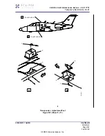
Страница 287: ...ONDER 1 A B B 1 2 3 2 1 4 Transponder Adjustment Test Figure 501 Sheet 1 of 1 EA500 Aircraft Maintenance Manual 06 117751 Temporary Revision No 34 21 EFFECTIVITY ALL POST MB 500 31 016 34 50 21 Page 5...
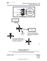
Страница 288: ...GS SHOULD BE AT OBLIQUE ANGLES OCCUPYING 20 BEAMWIDTH IFR 6000 TEST SET AND ANTENNA BUILDING BUILDING HANDLE TNG CONNECTION CABLE TO TEST SET FLAT ANTENNA ANTENNA PATTERN BEAMWIDTH 20 VERTICAL 25 HORI...
Страница 289: ...01 A Make sure that the aircraft is in same configuration as it was when the removal task was completed Refer to AMM 34 50 21 001 801 Transponder Removal B As required make sure that transponder is co...
Страница 290: ...ight Primary Flight Display PFD C Remove the warning placard D Do an adjustment test of the transponder system Refer to AMM 34 50 20 071 C 801 Transponder Adjustment Test E If all other maintenance is...
Страница 291: ...ARITY NOTE WING INSP R ENG L ENG WING Transponder Removal Installation Avio NG 1 5 display shown Figure 401 Sheet 1 of 1 EA500 Aircraft Maintenance Manual 06 117751 Temporary Revision No 34 21 EFFECTI...
Страница 292: ...EA500 Aircraft Maintenance Manual 06 117751 Temporary Revision No 34 21 THIS PAGE INTENTIONALLY LEFT BLANK EFFECTIVITY ALL 34 50 21 Page 404 Inst Sep 30 20 2020 Eclipse Aerospace Inc...
Страница 293: ...their respective diversity transponder s A Remove the protective caps from the electrical connectors B Put the transponder lower and or if installed upper antenna relay 1 on the structure and align t...
Страница 294: ...5 milliohms or less 4 Job Close Up SUBTASK AMM 34 50 23 041 921 002 A Remove all tools equipment and unwanted material from the work area B If removed install the air conditioning ducts Refer to AMM 2...
Страница 295: ...ation Avio NG 1 5 Display shown Figure 401 Sheet 1 of 1 EA500 Aircraft Maintenance Manual 06 117751 Temporary Revision No 34 21 EFFECTIVITY 0001 0104 0113 0115 0120 0123 0124 POST SB 500 99 002 0105 0...
Страница 296: ...Revision No 34 21 THIS PAGE INTENTIONALLY LEFT BLANK EFFECTIVITY 0001 0104 0113 0115 0120 0123 0124 POST SB 500 99 002 0105 0112 0116 0119 0121 0122 0125 0265 POST SB 500 99 005 AND 0266 0267 34 50 2...
Страница 297: ...ectrical connector 3 from switch body 6 with extraction tool 18 234 3 Identify the two extraction slots positioned on either side of the cap 7 Extract the switch cap 7 by using the Cap Extractor Tool...
Страница 298: ...emove switch body 6 from the bracket 1 EA500 Aircraft Maintenance Manual 06 117751 Temporary Revision No 34 21 EFFECTIVITY ALL POST MB 500 34 030 34 50 26 Page 402 Rem Sep 30 20 2020 Eclipse Aerospace...
Страница 299: ...Fail Indicator Removal Installation Figure 401 Sheet 1 of 2 EA500 Aircraft Maintenance Manual 06 117751 Temporary Revision No 34 21 EFFECTIVITY ALL POST MB 500 34 030 34 50 26 Page 403 Rem Sep 30 20 2...
Страница 300: ...S B Fail Indicator Removal Installation Figure 401 Sheet 2 of 2 EA500 Aircraft Maintenance Manual 06 117751 Temporary Revision No 34 21 EFFECTIVITY ALL POST MB 500 34 030 34 50 26 Page 404 Rem Sep 30...
Страница 301: ...the locking sleeve 4 onto the switch body 6 and sliding it forward against the mounting bracket 1 3 From the front of the switch body 6 locate the two slot head integral mounting screws 8 in the base...
Страница 302: ...l Test Refer to SUBTASK AMM 34 50 20 071 C 701 008 C If all other maintenance is complete return the aircraft to service Refer to AMM 20 00 02 051 801 Return To Service After Maintenance EA500 Aircraf...
Страница 303: ...Fail Indicator Removal Installation Figure 401 Sheet 1 of 2 EA500 Aircraft Maintenance Manual 06 117751 Temporary Revision No 34 21 EFFECTIVITY ALL POST MB 500 34 030 34 50 26 Page 403 Inst Sep 30 20...
Страница 304: ...B Fail Indicator Removal Installation Figure 401 Sheet 2 of 2 EA500 Aircraft Maintenance Manual 06 117751 Temporary Revision No 34 21 EFFECTIVITY ALL POST MB 500 34 030 34 50 26 Page 404 Inst Sep 30...