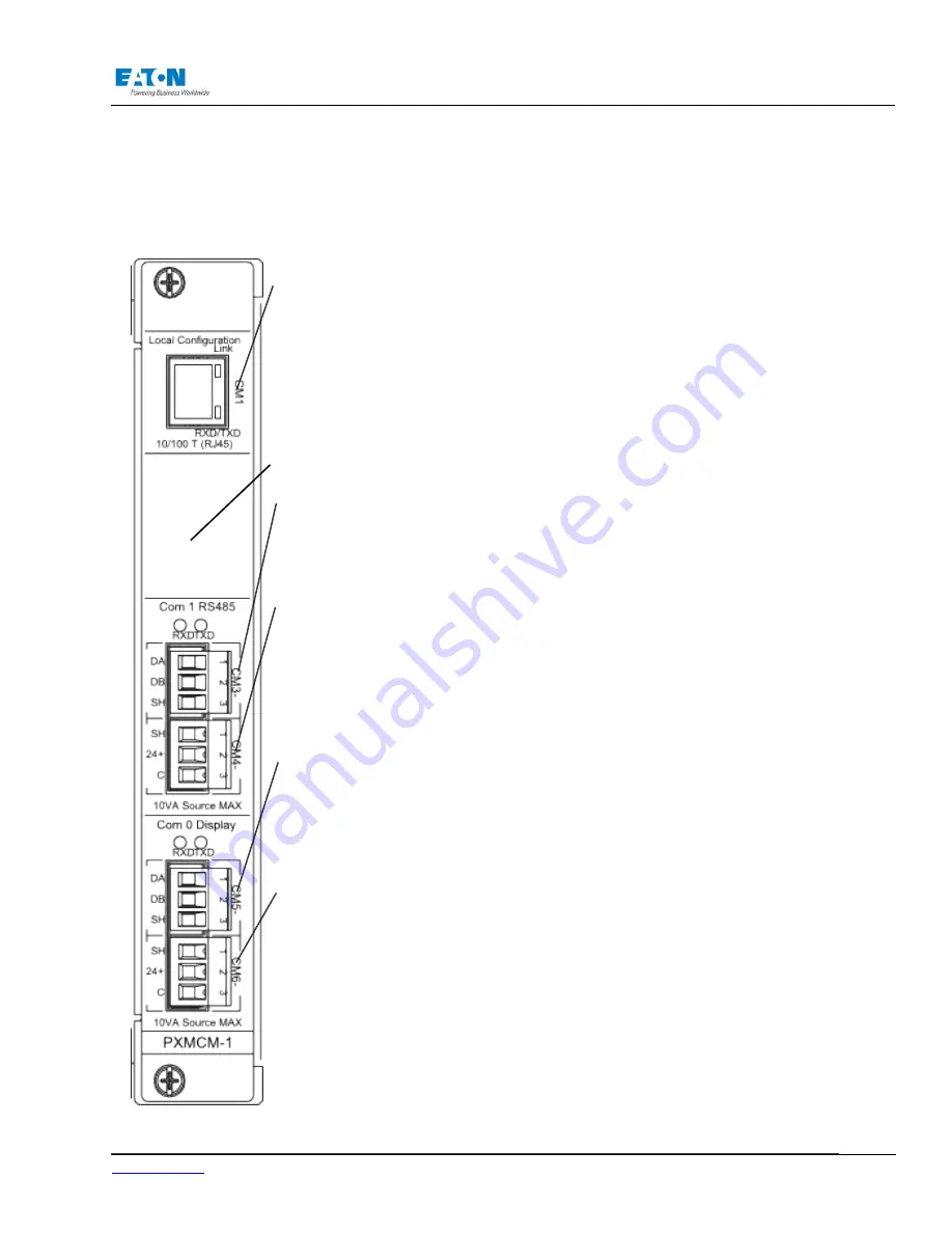
The PXMCM card is the default communication card in all Power Xpert Meters. Configura
-
tion can be accessed via the CM local configuration port or the Display.
CM1 – Local Configuration Port - Ethernet 10/100baseT RJ45 interface requires Cat 5
crossover cable. The IP address is fixed at 192.168.1.1 and is dedicated for configura-tion
of the meter (including serial ports) with a PC browser.
NOTE: This is NOT a LAN/WAN interface.
CM3 - COM1 – 3 terminal plug RS485 interface configurable as Modbus RTU Slave or
Gateway Master/Slave. Defaults to slave Gateway.
• CM31 Data A (-)
• CM32 Data B (+)
• CM33 Shield (RS485 common)
CM4 - 24Vdc 10W max - 3 terminal, gender inverted plug. Source for use with auxiliary
devices. (See following pages for further details.)
NOTE: This output is electrically common with CM3/COM1. Do not extend cable be-
yond 30M.
• CM41 Shield
• CM42 24V+
CM5 - COM0 - RS485 dedicated to remote Display interface for connection to DG1/
COM0 of the Display. The Meter address is assigned using the Rotary Switch found
below the meter left side CT terminal.
• CM51 Data A (-)
• CM52 Data B (+)
• CM53 Shield (RS485 common)
CM6 - 24Vdc 10W max – Used to power the Graphical Display if the cable distance is
less than 30M. If greater than 30M, use a separate 24V supply to power the Display.
• CM61 Shield
• CM62 24V+
• CM63 24V common
G.2. Communication Main (PXMCM) Card
Future Expansion
www.eaton.com
IM02601004E
Page 265
G Standard Cards
Содержание Power Xpert PXM 4000
Страница 1: ...User and Installation Manual IM02601004E Power Xpert PXM 4000 6000 8000 ...
Страница 8: ...Page vi IM02601004E www eaton ...
Страница 19: ...www eaton com IM02601004E Page 11 1 Introduction ...
Страница 24: ...Page 16 IM02601004E www eaton ...
Страница 36: ...Page 18 IM02601004E www eaton com 2 Quick Start Guide for the Meter Module ...
Страница 45: ...www eaton com IM02601004E Page 37 3 Installation 3 8 MeterDimensions ...
Страница 46: ...Page 38 IM02601004E www eaton 3 Installation Dimension Con t ...
Страница 47: ...www eaton com IM02601004E Page 39 3 Installation Dimension Con t ...
Страница 48: ...Page 40 IM02601004E www eaton 3 Installation Dimension Con t ...
Страница 53: ...www eaton com IM02601004E Page 45 3 Installation ...
Страница 54: ...Page 46 IM02601004E www eaton 3 Installation ...
Страница 55: ...www eaton com IM02601004E Page 47 3 Installation ...
Страница 56: ...Page 48 IM02601004E www eaton 3 Installation ...
Страница 57: ...www eaton com IM02601004E Page 49 3 Installation ...
Страница 58: ...Page 50 IM02601004E www eaton 3 Installation ...
Страница 59: ...www eaton com IM02601004E Page 51 3 Installation ...
Страница 60: ...Page 52 IM02601004E www eaton 3 Installation ...
Страница 61: ...www eaton com IM02601004E Page 53 3 Installation ...
Страница 62: ...Page 54 IM02601004E www eaton 3 Installation ...
Страница 63: ...www eaton com IM02601004E Page 55 3 Installation ...
Страница 66: ...Page 58 IM02601004E www eaton 3 Installation ...
Страница 75: ...www eaton com IM02601004E Page 67 4 Introduction to Web Server Screens ...
Страница 76: ...Page 68 IM02601004E www eaton 4 Introduction to Web Server Screens ...
Страница 86: ...Page 78 IM02601004E www eaton 5 Introduction to the Local Graphical Display ...
Страница 108: ...Page 100 IM02601004E www eaton 6 Functions on the Web Server Pages ...
Страница 128: ...Page 120 IM02601004E www eaton 7 Functions on the Graphical Display ...
Страница 164: ...Page 156 IM02601004E www eaton 8 Setup on the Web Server Pages ...
Страница 198: ...Page 190 IM02601004E www eaton A MODBUS Communication ...
Страница 242: ...Page 234 IM02601004E www eaton ...
Страница 252: ...Page 244 IM02601004E www eaton D Diagnostics ...
Страница 254: ...Page 246 IM02601004E www eaton D Diagnostics ...