Page 148
IM02601004E
www.eaton.
8 Setup on the Web Server Pages
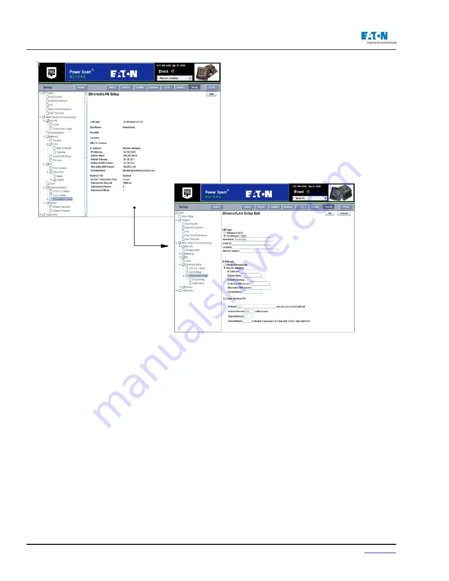
CONFIGURING MODBUS COMMUNICATIONS
When Modbus/TCP is enabled, it can be configured to accept connections from either all clients
or trusted clients. You can set this by entering the IP address mask. The X.X.X.X setting ac-
cepts all connections; however, you can also use the mask to accept connections from any client
within a given subnet. For example, 192.168.X.X allows connections from any client in the subnet
192.168.0.0 to 192.168.254.254.
You can also use the meter as a gateway to a Modbus subnet and the Ethernet/LAN Setup page
provides settings for configuring the gateway. Either RS-485 serial port can be configured as the
connection to the subnet; however, there are some tuning considerations, which are covered later,
that may affect the choice of port. Either of the two RS-485 ports, or the RS-232 port, can be desig-
nated Master-Gateway and Master-IO. These can be designated as such on the Com 1 & 2 Setup
Edit page, and the Com 3 Setup page.
MODBUS TUNING
Modbus clients can respond differently to polling commands and may require additional time to
respond. Also, the meter may need to attempt to poll a device multiple times as it may be in a state
that does not allow it to immediately reply and therefore exceed the timeout value. You can use
these settings to configure your the meter to accommodate the various requirements of the devices
on the subnet.
If there will be a high level of polling traffic, you should seriously consider having the Display Link
on a separate RS485 port from the Modbus subnet. A high level of polling traffic can degrade
Содержание Power Xpert PXM 4000
Страница 1: ...User and Installation Manual IM02601004E Power Xpert PXM 4000 6000 8000 ...
Страница 8: ...Page vi IM02601004E www eaton ...
Страница 19: ...www eaton com IM02601004E Page 11 1 Introduction ...
Страница 24: ...Page 16 IM02601004E www eaton ...
Страница 36: ...Page 18 IM02601004E www eaton com 2 Quick Start Guide for the Meter Module ...
Страница 45: ...www eaton com IM02601004E Page 37 3 Installation 3 8 MeterDimensions ...
Страница 46: ...Page 38 IM02601004E www eaton 3 Installation Dimension Con t ...
Страница 47: ...www eaton com IM02601004E Page 39 3 Installation Dimension Con t ...
Страница 48: ...Page 40 IM02601004E www eaton 3 Installation Dimension Con t ...
Страница 53: ...www eaton com IM02601004E Page 45 3 Installation ...
Страница 54: ...Page 46 IM02601004E www eaton 3 Installation ...
Страница 55: ...www eaton com IM02601004E Page 47 3 Installation ...
Страница 56: ...Page 48 IM02601004E www eaton 3 Installation ...
Страница 57: ...www eaton com IM02601004E Page 49 3 Installation ...
Страница 58: ...Page 50 IM02601004E www eaton 3 Installation ...
Страница 59: ...www eaton com IM02601004E Page 51 3 Installation ...
Страница 60: ...Page 52 IM02601004E www eaton 3 Installation ...
Страница 61: ...www eaton com IM02601004E Page 53 3 Installation ...
Страница 62: ...Page 54 IM02601004E www eaton 3 Installation ...
Страница 63: ...www eaton com IM02601004E Page 55 3 Installation ...
Страница 66: ...Page 58 IM02601004E www eaton 3 Installation ...
Страница 75: ...www eaton com IM02601004E Page 67 4 Introduction to Web Server Screens ...
Страница 76: ...Page 68 IM02601004E www eaton 4 Introduction to Web Server Screens ...
Страница 86: ...Page 78 IM02601004E www eaton 5 Introduction to the Local Graphical Display ...
Страница 108: ...Page 100 IM02601004E www eaton 6 Functions on the Web Server Pages ...
Страница 128: ...Page 120 IM02601004E www eaton 7 Functions on the Graphical Display ...
Страница 164: ...Page 156 IM02601004E www eaton 8 Setup on the Web Server Pages ...
Страница 198: ...Page 190 IM02601004E www eaton A MODBUS Communication ...
Страница 242: ...Page 234 IM02601004E www eaton ...
Страница 252: ...Page 244 IM02601004E www eaton D Diagnostics ...
Страница 254: ...Page 246 IM02601004E www eaton D Diagnostics ...